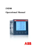
IM300 Intelligent Power Monitoring Instrument
11
AO+ AO- NC
NC
24 25 26 27
R
L
u
fig. 2-2-6 DC
analog outputs
wiring diagram
2.2.8. Wiring Precautions
The conductor cross section of the connecting wire to the device should meet the
following requirements: the cross section of current wires is not less than 2.5
mm
2
, the cross section of voltage wires is not less than 1.0 mm
2
.
Communication lines must be shielded twisted pair, communication line RS485 +,
RS485- can not be reversed.
The wires of power supply and voltage input must be connected with 2A fuse in
series..
To reduce the impact of current at startup, it is recommended each power cord
does not exceed 40 devices.
When the communication connection using the linear connection, respectively
access line should match 100 ~ 120Ω resistor is located between the beginning
and the ending of the communication cable at the RS485 + and RS485- terminals.
Baud rate is 9600bps, the cable length <1200 meters.
The maximum load of the analog outputs includes the line resistance. Be careful
when wiring.
3.
Operating Instructions
This chapter details IM300 man-machine interface, including how to read the
data, set parameters, and local operations.
Note:
IM300 means depending on each particular model (see Appendix C. ordering), does
not have a corresponding function corresponding to the interface does not display.
Summary of Contents for IM300-I
Page 1: ...IM300 Operational Manual ...
Page 109: ...CNABB CNIIB IM300 201903 REV C ...


