(9)
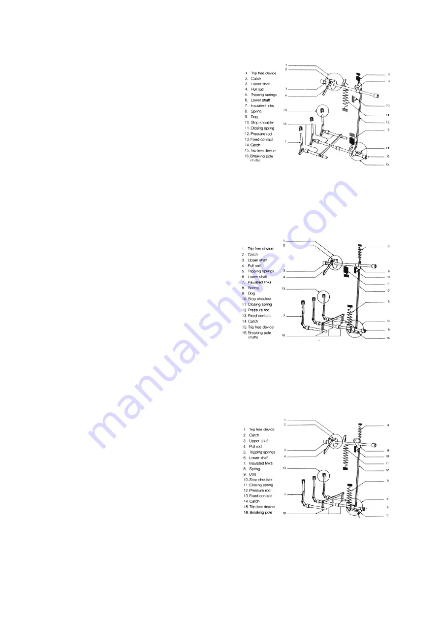
Operating Mechanism Working Principle:
Fig. 6A shows the operating device with
the breaker in the open position. The
closing spring (11) is charged if the latch
(2) is tripped, the upper shaft is released,
its turning is transmitted via link (12) to
the breaker pole shafts (6).
In fig. 6B the breaker has closed and at
the same time the opening spring (5) has
been charged. Driving disc (9) comes to
rest against stop (10) which, via link (12)
and trip free device (14) also prevents the
opening spring turning the breaker pole
shaft (6). Now the charging device starts
and link (4) moves upwards until latch (2)
is engaged. At this point link (4) turns and
begins to move downwards, whereupon
the upper shaft turns and retentions. The
closing spring position is reached
according to fig. 6C.
During the breaker opening, latch (14) is
released, thus releasing the lower shaft
which via the insulating links (7), actuates
the moving contact of the breaker poles,
for interruption. The spring (8) returns the
link (12) with the associated driving pin
and the operating device to the position in
fig. 6A.
For rapid re-closing the associated
switchgear cubicles can be fitted with
suitable relay equipment. The HPA can
be fitted with two opening coils, one
closing coils.
Fig - 6A
Fig - 6B
Fig - 6C
Summary of Contents for HPA 12kV
Page 7: ...Fig 3b HPA breaker pole for 36 kV ...
Page 9: ... 7 Fig 5 Circuit Breaker ...
Page 13: ...Fig 7A Maintenance schedule for frequently operated breaker type HPA 1VYN400290 005 11 ...
Page 14: ...Fig 7B Maintenance schedule for frequently operated breaker type HPA 1VYN400290 005 12 ...
Page 15: ...Electrical endurance HPA 13 ...
Page 29: ......


