background image


Page 6


© Copyright 2023 ABB. All rights reserved. 


GPS2436_MAN


               Rev. 1.3              


Power Systems product manuals and software are available on

-

line. Software includes Easy View and 

SNMP MIB.


Customer Service Contacts


Customer  Service,  Customer  Training,  Technical  Support,  Product 

Repair and Return, and Warranty Service


For  customers  in  the  United  States,  Canada,  Puerto  Rico,  and  the  US  Virgin  Islands,                                          

please  dial  +1  877  546  3243    or  for  all  other  countries,  please  call  +1  972  244  9288.  This  number  is 

staffed from 7:00 am to 5:00 pm USA Central Time Zone (GMT

-

6), Monday through Friday, on normal 

business days. At other times, this number is still available, but for emergencies only. Services provided 

include  initiating  the  spare  parts  procurement  process,  ordering  documents,  product  warranty 

administration, and providing other product and service information.


For other customers worldwide the 800 number may be accessed after first dialing the direct country 

code for the country where the call is originating, or you may contact your local field support center or 

your sales representative to discuss your specific needs.


On

-

Line Power Systems Product Manuals and Software


Summary of Contents for GPS2436

Page 1: ... specific to the Galaxy Millennium II controller Refer to these documents for information specific to the Galaxy Pulsar Plus controller Galaxy Pulsar Plus Product Manual CC848815341 GPS2436 Ordering Guide H5692436 Product Manual Ordering Code 850022020 Notice The information specifications and procedures in this manual are subject to change without notice ABB Power assumes no responsibility for an...

Page 2: ... Connection Panels 19 Overview 19 7 DC Distribution Panels 21 Function 21 8 External Return Bars 27 Overview 27 9 Millennium II Controller Operation 31 Controller Connections 33 Installing Circuit Packs 34 Thermal Probes 37 USB Interface 37 Local Port 37 Wiring Alarm Outputs 38 Wiring Alarm and Control Inputs 40 Fuses 44 Front Panel Display 44 Controller Defaults 47 Controller Display Menu Maps 53...

Page 3: ...63 11Circuit Boards 71 Overview 71 12 Specifications 73 GPS2436 73 Rectifier 75 13 Safety 77 Safety Statements 77 14 Maintenance and Replacement 79 Requirements 79 Rectifier Installation and Replacement Procedures 79 15 Troubleshooting Procedure 81 Preliminary 81 Troubleshooting Procedure 82 16 Product Warranty 83 17 Revision 85 ...

Page 4: ...Page 4 Copyright 2023 ABB All rights reserved GPS2436_MAN Rev 1 3 This Page is intentionally left blank ...

Page 5: ...vaults The main emphasis of this manual is to provide a general product description that will familiarize the user with the main components of the system and to provide guidelines for the basic maintenance of this Galaxy Power System GPS2436 is available with Galaxy Millennium or Galaxy Pulsar Plus controllers Both controllers provide many advanced functions and features including Alarm Detection ...

Page 6: ...r is staffed from 7 00 am to 5 00 pm USA Central Time Zone GMT 6 Monday through Friday on normal business days At other times this number is still available but for emergencies only Services provided include initiating the spare parts procurement process ordering documents product warranty administration and providing other product and service information For other customers worldwide the 800 numb...

Page 7: ...the commercial utility or a standby ac power source and rectifies it to produce dc power for the using equipment The system s control and alarm functions interact with the rectifiers and the office In addition the system provides overcurrent protection and charge discharge and distribution facilities Battery reserve is connected in parallel and automatically provides a source of dc power if the co...

Page 8: ...l provides overcurrent protection connection points for the using equipment and bus bars used to interconnect the rectifiers batteries and dc distribution Battery Connection Panel provides connection points for the battery strings through battery disconnect fuses or contactors and current monitoring shunts Architecture The GPS2436 is a 7 foot cabinet that can provide up to 3600 amps of DC power in...

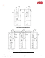
Page 9: ... Figure 2 3 Schematic of two cabinet system architecture Controller Rectifier Battery Distribution Cabinet Rectifier Battery Distribution Cabinet Rectifier Battery Distribution Cabinet Figure 2 4 Schematic of Three cabinet System Architecture 1800A Maximum per system ...

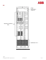
Page 10: ...ght 2023 ABB All rights reserved GPS2436_MAN Rev 1 3 Figure 2 5 GPS2436 Six shelf cabinet with door removed Rectifier Shelves 3 6 or 9 AC Panel Circuit Breakers or Terminal strip Miscellaneous DC Distribution Panels ...

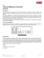
Page 11: ... acts as an interface to the cabinet control and alarm signals User Interface and Display The Millennium II s primary user interface is a backlit LCD front panel display that can be viewed in English or Spanish two rows of LEDs an array of pushbutton keys and a pair of test jacks Figure 3 1 illustrates the front panel Default Display The default display shows basic system status system voltage loa...

Page 12: ...group of pushbutton keys below the backlit LCD display provides the primary user interface with the controller These keys are used singly or in combination to navigate through the controller s menus The following is a general description of the pushbutton keys ESCAPE Return to the immediate higher level menu HELP Displays limited on line help information MENU View the MAIN menu ENTER Select a menu...

Page 13: ...llennium II Controller product manual Ordering Code 108994645 is available Refer to this manual for information regarding configuration and operation RPM System Product Manual Refer to the Galaxy Remote Peripheral Monitoring System product manual Ordering Code 107570517 for additional information regarding RPM module operation ...

Page 14: ...Page 14 Copyright 2023 ABB All rights reserved GPS2436_MAN Rev 1 3 This Page is intentionally left blank ...

Page 15: ...r s condition The Norm LED is green and is lit when the rectifier has AC input present and is working properly The ACF LED is amber and is lit when there is no AC input present to the rectifier The Fail LED is red and is lit if there is a failure in the rectifier Lamp Test To test the LEDs on the rectifier front panel press the Lamp Test button on the controller Features Output Current Walk in Out...

Page 16: ...emperature and will issue a thermal alarm if the internal temperature exceeds a safe operating level Ambient temperatures above the maximum rating will result in a rectifier shutdown and the issuing of a thermal alarm TA Autonomous Operation Rectifiers will continue to power the load if the controller fails or if communication is lost Controller Communications Alarm When communications between the...

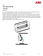
Page 17: ...4 wire three phases neutral or individual 2 wire single phase either 2 hot leads or 1 hot lead and neutral input ac service Some options provide circuit breakers to protect the conductors providing ac service to the individual rectifiers Other systems contain a terminal strip and the conductors are protected by circuit breakers located in the building s ac service panel Note All wire sizes based o...

Page 18: ...N Rev 1 3 Figure 5 3 AC Input circuit Breaker Panel CB1 CB2 CB3 CB4 CB5 CB6 CB7 CB8 CB9 CB10 CB11 CB12 G11 G12 G21 G22 G31 G32 G41 G42 G51 G52 G61 G62 G13 G14 G23 G24 G33 G34 G43 G44 G53 G54 G63 G64 Figure 5 4 AC circuit breaker wiring and rectifier positions ...

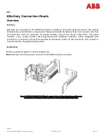
Page 19: ...us information The panel includes a low voltage battery disconnect reconnect LVBD R contactor When equipped with contactors a contactor control card provides local manual control of the contactors and a shunt to monitor battery charge discharge current Illustrations Battery connection panel is shown in Figures 6 1 Note Battery connection panels are blue dc distribution panels are white Figure 6 1 ...

Page 20: ...Page 20 Copyright 2023 ABB All rights reserved GPS2436_MAN Rev 1 3 This Page is intentionally left blank ...

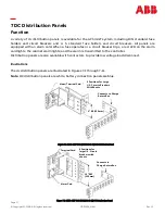
Page 21: ... is transmitted to the controller Distribution panels are also available with contactors to provide low voltage load disconnect Illustrations The dc distribution panels are illustrated in Figures 7 1 through 7 11 Note DC distribution panels are white battery connection panels are blue Figure 7 1 H569 4827 G42 ED83143 31 G2 DC Distribution Panel Figure 7 2 H569 4827 G43 ED83143 31 G1 DC Distributio...

Page 22: ... Figure 7 5 H569 4827 G52 ED83143 31 G53 DC Distribution Panel Terminal Card Alarm Card 5 Positions for large U S Circuit Breakers with shunts Connects to Charge Return Bus 9 REF 229mm Alarm Terminal Card 6 REF 152mm Connects to Charge Return Bus 10 Medium U S Fuse Holders Alarm Terminal Card Connects to Charge Return Bus 10 Positions for Plug in Bullet Style Circuit Breakers 6 REF 152mm ...

Page 23: ...D83143 31 G71 DC Distribution Panel 2600 Shunts 2 U S Large Fuse Holders Connects to Charge Return Bus Alarm Terminal Card 9 REF 229mm 14 Positions for DIN Circuit Breakers 1 63A or DIN Fuse Holders 10 x 38mm fuses 1 32A Or 10 Positions for DIN Circuit Breakers 80 125A or DIN Fuse Holders 14 x 51mm fuses 1 50A Connects to Charge Return Bus Alarm Cards 6 REF 152mm ...

Page 24: ...G68 ED83143 31 G21 DC Distribution Panel Alarm Terminal Card 8 NH00 Fuse Holders Connects to Charge Return Bus 6 REF 152mm Alarm Terminal Card 6 REF 152mm Connects to Charge Return Bus 2 NH2 Fuse Holders Alarm Terminal Card G97 6 REF 152mm G98 9 REF 229MM Connects to Charge Return Bus Figure 7 10 H569 4827 G97 G98 ED83143 31 G17 DC Distribution Panel ...

Page 25: ... Distribution Panel Alarm Terminal Card Connects to Charge Return Bus 9 REF 229mm 300A Shunt in back of panel Per position 5 Large TPL B Fuse Positions Maximum Panel Capacity 1125A 800A With LVLD Shunt Monitoring Connection Points to RPMS Connects to Charge Return Bus 6 REF 152mm TPL C Fuse Head Furnished With Block Order 408472322 TPL B Fuse Block Head for 70A 250A Fuses ...

Page 26: ...Page 26 Copyright 2023 ABB All rights reserved GPS2436_MAN Rev 1 3 This Page is intentionally left blank ...

Page 27: ... and offer additional cable landings Illustrations External return bars are illustrated in Figures 8 1 through 8 3 Figure 8 1 Standard Architecture 600mm External Return Bus Kit CC848805160 for distributed architecture cabinets 22 SETS OF 3 8 HOLES ON 1 INCH CENTERS FOR 750KCMIL CABLE 7 SETS OF 1 4 INCH HOLES ON 5 8 INCH CENTERS CC848805160 EXTERNAL RETURN BUS KIT FOT MOUNTING ON DISTRIBUTED ARCHI...

Page 28: ...served GPS2436_MAN Rev 1 3 Figure 8 2 Horizontal Rectifier Standard and Wide Distribution Bay bus bar system CC109170511 Standard Bay CC109170197 Wide Bay Modular Distribution Bay Overhead Buses CC109170180 Modular Rectifier Bay Overhead Bus ...

Page 29: ...reserved GPS2436_MAN Rev 1 3 CC109170412 Modular Distribution Wide Bay Overhead Bus Field Option A Field Option B Figure 8 3 Vertical rectifier standard and Wide distribution bay return bus bar systems CC109170404 Rectifier Bay Overhead Bus ...

Page 30: ...Page 30 Copyright 2023 ABB All rights reserved GPS2436_MAN Rev 1 3 This Page is intentionally left blank ...

Page 31: ...re anchored in place The battery stands have been erected and the batteries installed The overhead cable racks have been installed and the power cables have been run and terminated The plant s charge and discharge bus bar assemblies have been installed But BEFORE Connecting the batteries to the plant charge and discharge busbars or turning up the plant rectifiers Preparation Precautions Observe ES...

Page 32: ...1 Millennium II Installation Materials Item Verified Wire cutters and strippers 18 to 22 AWG wire Jewelers screwdriver Flat and Phillips Small needle nose pliers Digital meter 0 02 Screw Drivers flat blade and Phillips ESD wrist strap Wire wrap tool or Amp alarm punch down tool ...

Page 33: ... for isolated RS485 system component monitoring and control of rectifiers converters low voltage disconnect contactors and bay level alarm inputs Serial Rectifier bus P13 Factory test connector not used in the field P14 Connectorized interface for future smaller serial format LCD P15 Connectorized interface for future smaller serial format LCD P201 Connectorized interface for optional Modem P202 G...

Page 34: ...RJ11 connector and Ring is Pin 3 Pin 2is not used 5 Operate the reset switch on the MCR1 board in the lower left corner of theMCR1 board see Figure 4 3 NOTE The Password Reset button is to the LEFT of the serial port connector and the Controller Reset is to the right of the serial connector Data Switch Card Step Action NOTE Installation or replacement of this pack can be done hot power removal is ...

Page 35: ... the MCR2 board 2 Connect the other end to an IEEE 802 3 compatible network 3 Configure the Gateway for the network by contacting the customer s network administrator Detailed configuration information may be found inthe User s Guide for Millennium II Controller Advanced Features manual Rectifier Cabling Step Action NOTE For new installations the Millennium II rectifier cabling has been factory wi...

Page 36: ...odule connection unit and route the wires through the open faced bottom of the connection unit 4 Make the connections to TB2 on the connection unit 5 Locate the control unit This is the half with circuitry on it 6 In the lower right hand side of the control unit inside are two rotary switches Set SW 1 LO to 1 The module will be recognized as 01 by the controller Other modules added cannot have the...

Page 37: ...e and battery management information may be found in the User s Guide for Millennium II Controller Advanced Features manual 1 The following table shows the type of probe and connector location on the Millennium Type of Probe Ordering Code Controller Connection Location 10 30K P3 210E Thermal Probe Mux P3 1 Wire Temperature Monitoring Devices P7 Terminal Block Interface for 3 additional 10k probes ...

Page 38: ...AMN 3 PCRAR 35 MNFC 67 TFLT 4 PCRVR 36 MNFO 68 TBST 5 PCRVC 37 BDO 69 TRTN 6 PCRVO 38 BDC 70 PBTR 7 PCREO 39 BDR 71 PBT 8 PCREC 40 ACFR 72 OS 9 PCRER 41 ACFC 73 TR1 10 PMJAR 42 ACFO 74 TEQ 11 PMJAC 43 RFAO 75 ETR 12 PMJAO 44 RFAC 76 ETRR 13 PMJEO 45 RFAR 77 RO 14 PMJEC 46 HVR 78 ROR 15 PMJER 47 HVC 79 TR2 16 PMJVR 48 HVO 80 TR4 17 PMJVC 49 UR1O 81 RBRPO 18 PMJVO 50 UR1C 82 TBD now general I O 1 19...

Page 39: ...Power Major Audio 10 PMJAR 11 PMJAC 12 PMJAO Power Major External 13 PMJEO 14 PMJEC 15 PMJER Power Major Visual 16 PMJVR 17 PMJVC 18 PMJVO Power Minor Audio 19 PMNAO 20 PMNAC 21 PMNAR Power Minor Visual 22 PMNVR 23 PMNVC 24 PMNVO Power Minor External 28 PMNER 29 PMNEC 30 PMNEO Major Fuse 31 MJFO 32 MJFC 33 MJFR Minor Fuse 34 MNFR 35 MNFC 36 MNFO Battery On Discharge 37 BDO 38 BDC 39 BDR ...

Page 40: ... In a standard Galaxy Power System configuration plant level alarms are sent to the controller via the Bay Interface Card through serial data communication The following alarm inputs are provided for discretionary use in non standard applications Alarm Pin Number Signal Name Low Voltage 2 Disconnect State Detect 61 LVD2 Fuse Alarm Major 63 FAJ Fuse Alarm Minor 65 FAN Auxiliary Alarm Major 64 AMJ A...

Page 41: ... RBRPO General Purpose Input 1 82 IN 1 BTP or General Purpose Input 2 83 IN 2 BTP Low Voltage 1 Disconnect State Detect 84 LVD1 Transfer Rectifier 3 85 TR3 General Purpose 4 20mA Measuring Circuit 87 4 20mA General Purpose 4 20mA Measuring Circuit RTN 88 4 20mAR BTPFLT or Generic Input 3 89 IN 3 BTPFLT Low Voltage 3 Disconnect State Detect Also Battery Thermal Protect Major 90 LVD3 BTMJ General Pu...

Page 42: ...ed which must use an external 1K ohm 2W current limiting resistor at the source if not using standard ABB Power LVD circuit boards or controller This circuit is used to inform Galaxy that the monitoring circuit of a Low Voltage Disconnect device has failed In standard Galaxy Power Systems the Bay Interface board monitors these alarms and informs the Controller through the serial interface connecti...

Page 43: ...se features is to be configured in Galaxy software a battery temperature input must be connected to P3 temperature probe connector on the Controller board Three optional cables are used to connect to various battery arrangements Cable Assembly Connects to 848152997 KS20472 round cell thermistor 848152989 ring or paddle type thermistors 848153003 210E Thermal Probe Multiplexer Refer to User s Guide...

Page 44: ...s user interface is a panel that includes a backlit LCD module two sections of status LEDs system voltage test jacks and an array of simple push button controls This controller supports multiple LCD display assemblies It is backwards compatible to both existing Millennium LCD assemblies L51 and L50 shown in Figure 10 5 It is also compatible with the enhanced L52 LCD display assembly see figure 4 6...

Page 45: ...ws of LEDs at the right side of the interface board or two columns of LEDs at the left side of the interface board as seen in figure 4 5 The segregated sections of LEDs provide an indication of the alarm source rectifier battery distribution communication controller remote modules and the severity Critical Major Minor Nominal of the various alarms Operation of the status LEDs can be reconfigured v...

Page 46: ...this key to save a value that has been changed orto select a menu item ESCAPE Use this key to abort a change or to go back to theimmediate higher level menu Lamp Test Use this key to test the display and LEDs Test Jacks The Millennium II LCD panel assemblies also provide test jacks to provide the ability of using an external meter to monitor the Plant Voltage as seen in figure 4 7 Voltages to the ...

Page 47: ...nium has 8 dip switch positions SW202 that may be changed SW202 is located on the MCR1 board above the MCR2 board See figure 4 7 Figure 9 7 Millennium II Controller Dip Switches Switch Position Default Description Closed 1 Open 0 SW202 8 1 Front Panel Configuration ENABLED DISABLED SW202 7 0 Modem Aux Local Gateway USB IRDA Port Setting Configuration Remote Access ENABLED DISABLED SW202 6 0 Enhanc...

Page 48: ... Shutdown Threshold Change Rectifier Float Set Point Change Rectifier Boost Set Point Change Rectifier Boost Current Limit Change Converter Voltage Set Point Change Converter Low Voltage Disconnect Threshold Change Converter Low Voltage Reconnect Threshold Enable or disable Converter Low Voltage Disconnect feature Change Converter Status to Standby Vacant status is prohibited The change to On stat...

Page 49: ...0 00 25 00 22 00 48V 40 00 51 00 44 00 Table 9 I Voltage Threshold Ranges and Default Values Controller Alarm Severity LED and Relay Default Values Symbol Default Designation Default Severity Default LED Default Relay AAC ACO Active RO None None ABS Alarm Battery Supply Fuse Major CTLR CTLR AMJ Auxiliary Major Major None None AMN Auxiliary Minor Minor None None ATA Alarm Test Active RO None None A...

Page 50: ...e COR Number Did Not Respond Warning None None CPA Circuit Pack Fail Major CTLR CTLR CRA Controller Fail Major CTLR CTLR DID Rectifier ID Conflict Major RECT None EMD Energy Management Disabled Warning None None EPD Excess Plant Drain Minor RECT None EPO Emergency Power Off Critical BATT None EPR External Password Reset Warning None None ETO Engine Transfer Timeout Minor AC None EXL Excessive Logi...

Page 51: ...LR URC User Relay Conflict Warning None None VLA Very Low Voltage Critical BAT UR3 VSF Sense Control Fuse Major CTLR CTLR ZID ID Not Configured Major RECT None Table 9 K Rectifier Alarm Defaults Table 9 J Controller Alarm Severity LED and Relay Default Values Symbol Default Designation Default Severity Default LED Default Relay ACF AC Fail Minor AC ACF CLM Rectifier Current Limit RO None None ERD ...

Page 52: ...e screen shows Plant Voltage Plant Load Current The bottom line s show An Hourglass may appear in the lower left hand corner of the screen This indicates that a configuration change is being saved to non volatile memory Audible Alarm Cutoff State Toggle Only shown if an alarm is active Plant Mode Default Float Screen information is updated approximately every two seconds The front panel display of...

Page 53: ...Page 53 Copyright 2023 ABB All rights reserved GPS2436_MAN Rev 1 3 Controller Display Menu Maps Configuration Menu Map ...

Page 54: ...Page 54 Copyright 2023 ABB All rights reserved GPS2436_MAN Rev 1 3 Control and Operations Menu Map ...

Page 55: ...Page 55 Copyright 2023 ABB All rights reserved GPS2436_MAN Rev 1 3 Status Menu Map ...

Page 56: ...Page 56 Copyright 2023 ABB All rights reserved GPS2436_MAN Rev 1 3 History Menu Map Statistics Menu Map ...

Page 57: ...note that the system will validate the entries before the system date is modified 2 TIME Format This field allows you to select one of the following time display formats 12 or 24 hour Use the or key to select the desired format and press ENTER to save the change Time Allows you to change set the time Daylight Enables or Disables Daylight Savings Minimum Configuration Front Panel The Millennium II ...

Page 58: ...e selected A maximum of two shunts of the same amperage can be connected through P6 on the BSH A shunt type of LOAD means that a load shunt located between load and plant bus bars is connected The load current displayed on the front panel is the sum of the two shunt currents A shunt type of BATTERY means that a battery shunt located between the batteries and plant bus bars is connected The load cu...

Page 59: ...ly due to an adjustment in the plant rather than due to a failure This alarm allows the High Voltage HV shutdown threshold to be raised slightly thus reducing the number of nuisance shutdowns without decreasing the plant reliability Move the cursor to the fields and use the or key to adjust the High Voltage shut down alarm for FLOAT mode to the desired level normally less than the HV threshold Pre...

Page 60: ...efined battery types used in reserve time prediction and enhanced battery test features Move the cursor to the field and use the or key to adjust the threshold value Press ENTER to save the change Strings The configuration of this field selects the number of battery strings in the system This parameter is used in reserve time prediction and enhanced battery test features Move the cursor to the fie...

Page 61: ...High Temp Comp This feature allows the system to compensate for high temperatures Volt StepDown Battery step temperature can be set from 113 185F At this temperature the system voltage is reduced by 0 17 X of cells string High Comp Limit This sets the maximum temperature for which thermal compensation is active Decrease This sets the slope mV degC for high temperature compensation NominalTemp This...

Page 62: ...the type chosen here For standard GPS configurations using BIC cards Contactor 1 is wired to and controls all BATTERY contactors in the plant Contactors 2 and 3 are wired to and control only LOAD contactors To toggle between the various contactor types move the cursor to one of the fields and use the or key to select the desired type Press ENTER to save the change Disconnect This setting configure...

Page 63: ...ersonnel Test Sequences Lamp Test This test verifies that All of the LEDs on the front panel of the controller are functioning properly No alarms are generated from this test Step Action 1 From the Default Screen press the Menu button for the Main Menu 2 Using the Up Down Arrows Scroll to Control Operations and press Enter 3 Select Start Lamp Test and press Enter 4 Press Enter again to start the t...

Page 64: ... the Enter key to reset the voltage This will remove any pre existing user calibrated values if they exist 2 Wait at least 5 seconds and press the ESCAPE key 3 Select CALIBRATE VOLTAGE Use the Arrows and UP DOWN keys to calibrate the system voltage Press ENTER to save NOTE The controller will not allow changes greater than 0 5V of the displayed voltage 4 Press the ESCAPE key until the default scre...

Page 65: ...on procedure Observation Displayed System load changes to new value High Float Voltage Alarm New Installations Step Action for Testing the High Float Voltage Alarm NOTE Clear all controller alarms for this test NOTE The high voltage alarm test is completed by raising the plant voltage above the threshold set for HFV High Float Voltage NOTE Raising the plant voltage on a working system is left to t...

Page 66: ...to the application of office load and batteries are connected NOTE 1 The plant voltage must be above the level set for the High Voltage alarm at the VOLTAGE ALARMS menu screen MENU CONFIGURE FLOAT SETTINGS VOLTAGE ALARMS 2 The rectifier must be delivering a current of at least 10 of its capacity 3 The rectifier s current output must be unbalanced by more than 10 from the average output cur rents o...

Page 67: ...EDon the rectifier is not lit After 5 6 seconds the rectifier initiates its own restart signal again raising the plant voltage The rectifier will shutdown and restart two additional times Upon the third shutdown the rectifier s ALM LED lightsand the rectifier s display indicates HO The controller receives the RFA signal from the rectifier and initiates a restart signal 5 6 seconds later The rectif...

Page 68: ...extinguished Rectifier Observations Rectifier is operating normally Battery on Discharge Alarm STEP Action for Testing the Battery on Discharge Alarm NOTE If the BD alarm was observed during the High Voltage Shutdown test this test can be disregarded 1 From the front panel follow the path Voltage Alarms 2 Note the setting of the Battery on Discharge Threshold 3 With a dummy load added to the plant...

Page 69: ...arms should be tested in each distribution bay of the plant to verify the integrity ofthe alarm bus throughout the plant If the distribution bays are equipped with Bay Fuse Alarm indicating LEDs also verifythat this LED activates during these tests for the bay in which the alarm originates and not in any other Clear History This feature is useful when there is a need to remove unnecessary historic...

Page 70: ...Page 70 Copyright 2023 ABB All rights reserved GPS2436_MAN Rev 1 3 This Page is intentionally left blank ...

Page 71: ...n the panel Provide alarm data to the controller Alarm Terminal Boards Alarm terminal boards combine the functions of alarm boards and terminal boards BLJ Terminal Board The BLJ terminal board is located inside the cabinet door The BLJ is the termination point for all signal cables in each cabinet and between cabinets Contactor Control Board installed only on systems with contactors Contactor cont...

Page 72: ...Page 72 Copyright 2023 ABB All rights reserved GPS2436_MAN Rev 1 3 This Page is intentionally left blank ...

Page 73: ...2 3 shelf cabinet 10 gauge 6 mm2 per rectifier for individual feeds 2 gauge 35 mm2 1 shelf cabinet 2 x 2 gauge 35 mm2 2 shelf cabinet 2 x 1 0 gauge 50 mm2 3 shelf cabinet 8 gauge 10 mm2 per rectifier for individual feeds Cabinet Output 24V Output Current 100 2000A System Output 24V 2 x Full Height Maximum System Output Current 100 2000A 2000A Mechanical Cabinet Full Height Nominal Cabinet Dimensio...

Page 74: ... Environmental Operating Ambient Temperature NE100AC24ATEZ 40 C to 75 C Altitude 50 to 4000 meters Note For altitudes between 1500 and 4000 meters derate the maximum temperature by 0 656 C per 100 meters Humidity 5 to 95 non condensing Radiated and Conducted EmissionsEN50082 1 EN50082 2 EN50081 EN61000 Electromagnetic Immunity Level B Earthquake Rating Zone 4 upper floors Standards Compliance Agen...

Page 75: ...characteristics of the rectifiers are as follows Phase to Phase Voltage MOV Conduction Current 320Vac RMS 0A 620V maximum clamping 1mA DC test current 810Vpeak 100A peak 8 x 20 s Output All High Voltage Shutdown Internal Selective High Voltage Shutdown ISHVSD Backup High Voltage Shutdown BUHVSD Float 56 0Vdc Nom 1 2 Boost 56 0Vdc Nom 1 2 Equalize 59 52 1Vdc Nom 1 2 Float Boost 59 52Vdc3 Equalize 6...

Page 76: ...lbs 9 kg Environmental Efficiency 90 typical Heat Release NE100AC24ATEZ 52Vdc 40A 52Vdc 50A 54 5Vdc 40A 54 5Vdc 50A 55Vdc 55A NE100AC24ATEZTEZ 52Vdc 80A 52Vdc 100A 54 5Vdc 80A 54 5Vdc 100A 54 5Vdc 110A Per rectifier 231W 788 9 BTU hr 288W 983 BTU hr 242W 827 BTU hr 302W 1 030 BTU hr 332W 1 133 BTU hr 463W 1 578 BTU hr 577W 1 966 BTU hr 485W 1 654 BTU hr 605W 2 060 BTU hr 666W 2 266 BTU hr Storage ...

Page 77: ...h the NE050AC48ATEZ has not been evaluated for hot swapping If the proper connector for the country of installation is not provided obtain appropriate connectors and follow manufacturers and all local requirements forproper connections All national and local rules and regulations should be followed when making field connections All input and output connections comply with SELV requirements Insulat...

Page 78: ...Page 78 Copyright 2023 ABB All rights reserved GPS2436_MAN Rev 1 3 This Page is intentionally left blank ...

Page 79: ...on 1 Locate and turn off the ac service to the rectifier positionthat is being installed or replaced Note Do not turn off ac service to the entire system only to the rectifier position that is being installed or replaced 2 Caution Rear portion of the rectifier that is in operation may be HOT to the touch Use appropriate precautions 3 This step is for replacement only For a new installation proceed...

Page 80: ...Page 80 Copyright 2023 ABB All rights reserved GPS2436_MAN Rev 1 3 This Page is intentionally left blank ...

Page 81: ...eshooting the GPS2436 Hazardous ac and dc voltages and or energy are present Caution should be exercised Tools must be insulated to help prevent accidental contact with live surfaces Coordinate all troubleshooting activities with other personnel that may be working on the system Table 1 Warnings Tools The following tools are necessary in order to troubleshoot the GPS2436 Calibrated digital voltmet...

Page 82: ...Ds will be illuminated Depending on the controller type the following will be displayed system voltage system current system mode system number of alarm warnings If the screen is blank but alarm and status LEDs are illuminated call technical support If the entire panel is blank check the controller fuses Verify that the controller is getting power If not replace fuse If the display is still blank ...

Page 83: ...tion charges if installed by Seller Where Seller has elected to repair a Seller s Manufactured Product other than Cable and Wire Products which has been installed by Seller and Seller ascertains that the Product is not readily returnable for repair Seller will repair the Product at Customer s site With respect to Cable and Wire Products manufactured by Seller which Seller elects to repair but whic...

Page 84: ...th respect to Products which have had their serial numbers or month and year of manufacture removed altered or experimental products or prototypes or with respect to expendable items including without limitation fuses light bulbs motor brushes and the like Seller s warranty does not extend to any system into which the Product is incorporated This warranty applies to Customer only and may notbe ass...

Page 85: ...Page 85 Copyright 2023 ABB All rights reserved GPS2436_MAN Rev 1 3 17 Revision Rev Description Date Dept Init 1 2 Updated as per template 11 12 2021 1 3 Updated page footer 3 30 2023 ...

Page 86: ... not accept any responsibility whatsoever for potential errors or possible lack of information in this document We reserve all rights in this document and in the subject matter and illustrations contained therein Any reproduction disclosure to third parties or utilization of its contents in whole or in parts is forbidden without prior written consent of ABB Copyright 2021 ABB All rights reserved A...

Reviews: