


Mounting
30
FV4000-VT4/VR4 / FS4000-ST4/SR4
D184B097U02
4.6
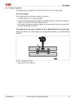
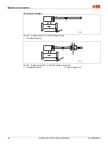
Installation of final controlling equipment
4.6.1 Vortex
flowmeter
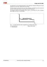
Final controlling equipment must be arranged at the outflow end spaced at a minimum 5 x DN.
G00615
50 x D
5 x D
Fig. 17: Installation of final controlling equipment
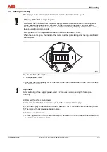
4.6.2 Vortex and Swirl flowmeters
If the medium is conveyed through piston/plunger pumps or compressors (pressures for fluids
> 10 bar (145 psi)), it may be subject to hydraulic vibration in the pipeline when the valve is
closed. If this does occur, the valve absolutely has to be installed in the flow direction upstream
of the flowmeter. Suitable dampers (e. g. air vessels in the case of pumping using a
compressor) might need to be used.
Summary of Contents for FS4000-SR4
Page 125: ...Appendix D184B097U02 FV4000 VT4 VR4 FS4000 ST4 SR4 125 ...
Page 126: ...Appendix 126 FV4000 VT4 VR4 FS4000 ST4 SR4 D184B097U02 ...
Page 127: ...Appendix D184B097U02 FV4000 VT4 VR4 FS4000 ST4 SR4 127 ...
Page 128: ...Appendix 128 FV4000 VT4 VR4 FS4000 ST4 SR4 D184B097U02 ...
Page 129: ...Appendix D184B097U02 FV4000 VT4 VR4 FS4000 ST4 SR4 129 ...
Page 135: ......


