


Mounting
28
FV4000-VT4/VR4 / FS4000-ST4/SR4
D184B097U02
4.3
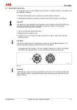
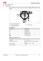
Recommended inflow and outflow sections
4.3.1 Vortex
flowmeter
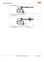
In order to maximize operational reliability, the flow profile at the inflow end must not be
distorted if at all possible. Provision should be made for an inflow section measuring approx. 15
times the nominal diameter. At elbows, the inflow section should measure at least 25 times the
nominal diameter, at round elbows 40 times the nominal diameter and where shutoff valves
appear in the inflow section, 50 times the nominal diameter. A value 5 times the size of the
nominal diameter is required at the outflow end.
G00703
15xD
5xD
15xD
5xD
18xD
5xD
25xD
5xD
20xD
5xD
50xD
5xD
40xD
5xD
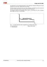
Fig. 13: Recommended inflow and outflow sections
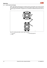
4.3.2 Swirl
flowmeter
On account of its operating principle, the Swirl flowmeter functions virtually without inflow and
outflow sections. The figure below shows the recommended inflow and outflow sections for
various installations. Inflow and outflow sections are not required if the elbow radius of single or
double pipe elbows upstream and downstream of the meter is greater than 1.8 x D. Similarly,
additional inflow and outflow sections are not required downstream of reductions with flange
transition pieces conforming to DIN 28545 (
α
/2 = 8°).
G00704
3D
1D
3D
1D
min 1,8 D
3D
1D
5D
1D
3D
3D
3D
3D
Fig. 14: Recommended inflow and outflow sections
Summary of Contents for FS4000-SR4
Page 125: ...Appendix D184B097U02 FV4000 VT4 VR4 FS4000 ST4 SR4 125 ...
Page 126: ...Appendix 126 FV4000 VT4 VR4 FS4000 ST4 SR4 D184B097U02 ...
Page 127: ...Appendix D184B097U02 FV4000 VT4 VR4 FS4000 ST4 SR4 127 ...
Page 128: ...Appendix 128 FV4000 VT4 VR4 FS4000 ST4 SR4 D184B097U02 ...
Page 129: ...Appendix D184B097U02 FV4000 VT4 VR4 FS4000 ST4 SR4 129 ...
Page 135: ......


