

Start-up
When the module is connected to the drive, the drive control program sets the applicable parameters.
See the appropriate drive manual.
Basic parameter settings
To take the settings into use, validate and refresh the parameters with parameter
51.27 FBA par refresh
.
Further information
Index
Name
Value
20.01
Ext1 commands
Fieldbus A
22.11
Speed ref1 source
FBA A ref 1
28.11
Frequency ref1 source
FBA A ref 1
50.01
FBA A enable
Enable (or select the option slot in which the module is installed).
This activates the communication module. The HOST LED becomes green.
50.02
FBA A comm loss func
Fault
51.02
MAC ID
Set the MAC ID number for the drive.
See the latest version of
FDNA-01 DeviceNet adapter
module user's manual
(3AFE68573360 [English]) in ABB
www.abb.com/drives/documents
)
.
new.abb.com/drives/connectivity/fieldbus-connectivity
).
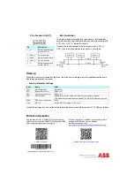
Pin allocation for [X1]
Bus termination
The module does not provide bus termination. The DeviceNet
network should be terminated at both ends of the trunk cable with
a 121 ohm, ¼ W, 1% metal film resistor.
Connect the resistor between the two signal wires (CAN_H,
CAN_L) on the DeviceNet cable, as shown in this figure.
Pin
Description
1
V-
Network power supply
ground (0V DC)
2
CAN_L
CAN_L bus line
3
SHLD
Network cable shield
4
CAN_H
CAN_H bus line
5
V+
Network power supply
source (24V DC)
1 2 3 4 5
Node 1
Node n
121
CAN_H
CAN_L
Scanner
121
1%
Metal Film
1/4 W
1%
Metal Film
1/4 W
…
3AXD50000158515 Rev A (EN) 2017-11-23


