ABB FAM3200 Series Manual Download Page 8

FAM3200

 ARMORED VARIABLE AREA PURGEMETER  |  CI/FAM3200-EN REV. D 
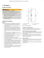


… 5  Installation 


… Installation conditions 


Heat tracing 


Trace heating may be used under the following conditions: 

•  The heat tracing must be installed such to make sure that 

there are no temperature increases in the indicator 
housing. 

•  The maximum permitted temperature of the heat tracing 

must not up-scale the permitted measuring medium 
temperature. 

•  When using electrical heat tracing, attention must be paid 

to potential functional impairment by electromagnetic 
fields. 


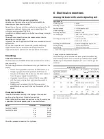
Operating conditions 


A variable area flowmeter is specified for a defined set of 
operating conditions of the measuring medium. For liquids and 
gases, these are pressure and temperature-related properties 
(density and viscosity) under operating conditions. 
For gases, in particular, this means operating at a specific 
operating pressure and operating temperature. The specified 
accuracy of the device always refers to the operating conditions 
underlying the specification. 
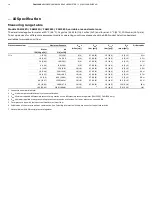


Pressure loss 

The available operating pressure at the measuring point must be 
higher than the pressure loss listed for the flowmeter in the 
specifications. 
It is important to also consider the pressure loss downstream 
from the flowmeter due to losses in the piping and other 
fittings. 


For information on pressure loss of the devices, see 

Measuring 

range table

 on page 14. 


Prevention of compression oscillations when measuring 
gases 

During low flow amounts and low operating pressure, so-called 
compression oscillations of the float can occur. 
If the maximum upstream pressure listed in the specifications is 
not reached, the flowmeter can optionally be equipped with a 
mechanical float damper.  
Damping is available for the device types FAM3225 and FAM3255 
with a process connection size > ¼ in. 
 
To prevent self-generated compression oscillations, note the 
following information from VDI / VDE 3513 Sheet 3: 

•  Select a flowmeter with the lowest possible pressure loss. 
•  Minimize the piping length between the flowmeter and 

the nearest upstream or downstream throttling location. 

•  Set the limit of the regular measuring range from the 

usual 10 to 100 % to 25 to 100 %. 

•  When setting the flow rate value, always start by 

assuming larger values. 

•  Increase the operating pressure and consider its effect 

on the flow rate changes due to the change in gas density 
in the operating conditions. 

•  Minimize non-throttled, free volumes upstream and 

downstream of the device. 


Pressure shocks 

Especially when measuring gases, it is possible that pressure or 
shock waves can occur when fast opening solenoid valves are 
employed and the piping cross-sections are not throttled, or if 
there are gas bubbles in liquids. 
As a result of the sudden expansion of the gas in the piping, the 
float is forcibly driven against the upper floatstop. 
Under certain conditions, this can lead to destruction of the 
device. 
The mechanical float damping is not suitable for the 
compensation of pressure shocks! 


Summary of Contents for FAM3200 Series

Page 1: ...le Area Purgemeter Measurement made easy FAM3200 Introduction Armored variable area purgemeters for measuring small flows of gases and liquids Additional Information Additional documentation on FAM320...

Page 2: ...s 8 Pressure loss 8 Prevention of compression oscillations when measuring gases 8 Pressure shocks 8 Solids content in the measuring medium 9 Mounting 9 General information 9 Flowmeter installation 9 6...

Page 3: ...he product may only be performed if expressly permitted by these instructions Information and symbols on the product must be observed These may not be removed and must be fully legible at all times Th...

Page 4: ...measuring media may only be used if the operator is able to perform regular and suitable tests to ensure the safe condition of the device The operator bears sole responsibility for the use of the devi...

Page 5: ...follower system 6 Cable entry Figure 1 Setup example The devices are used for local indication of the current flow rate with integrated alarm signalling units as flow rate monitors or with differenti...

Page 6: ...he shipper without delay and before installation Transport The center of gravity of some devices is not at the center of the equipment Use any of the available attachment points on the device for tran...

Page 7: ...and sudden pressure surges Use valves which open slowly If the flowmeter is installed in a pipeline where decommissioning is impossible or inexpedient a bypass line should be provided For gaseous mea...

Page 8: ...ntion of compression oscillations when measuring gases During low flow amounts and low operating pressure so called compression oscillations of the float can occur If the maximum upstream pressure lis...

Page 9: ...installation Install the flowmeter centrally in the piping at the required position using the correct threaded connections When tightening the process connections on the flowmeter use a spanner of the...

Page 10: ...position transmitter in two wire technology Other cable lengths available on request 7 Commissioning CAUTION Risk of burns due to hot measuring media The device surface temperature may exceed 70 C 158...

Page 11: ...s Repair and maintenance activities may only be performed by authorized customer service personnel When replacing or repairing individual components use original spare parts Note Spare parts can be or...

Page 12: ...s conditions The process conditions for example high pressures and temperatures toxic and aggressive measuring media can give rise to hazards when dismantling the device If necessary wear suited perso...

Page 13: ...Material load Figure 7 PS pressure TS temperature Maximum permissible operating pressure The permissible operating pressure is dependent on the optional device equipment Model Option Max permissible o...

Page 14: ...0 7 10 15 1 0 14 5 8 0 12 04H 6 1 59 230 8 12 18 18 0 7 10 15 1 0 14 5 8 0 12 05H 10 2 64 350 12 36 18 18 0 7 10 15 1 0 14 5 8 0 12 06H 16 4 23 540 19 07 18 18 0 7 10 15 1 0 14 5 8 0 12 07H 25 6 6 850...

Page 15: ...4 0 58 02 0 3 4 35 85 1 23 31H 600 158 5 18000 635 66 8 8 4 0 58 02 0 3 4 35 95 1 38 32H 700 184 92 21000 5547 61 8 8 4 0 58 02 0 3 4 35 105 1 53 33H 800 211 34 24000 847 55 8 8 4 0 58 02 0 3 4 35 13...

Page 16: ...mentation declarations of conformity and certificates are available in ABB s download area www abb com flow Trademarks Buna N is a registered trademark of DuPont Dow Elastomers Kalrez and Kalrez Spect...

Page 17: ...Company Address Contact person Telephone Fax Email Device details Type Serial no Reason for the return description of the defect Was this device used in conjunction with substances which pose a threa...

Page 18: ...18 FAM3200 ARMORED VARIABLE AREA PURGEMETER CI FAM3200 EN REV D Notes...

Page 19: ...FAM3200 ARMORED VARIABLE AREA PURGEMETER CI FAM3200 EN REV D 19 Notes...

Page 20: ...ice With regard to purchase orders the agreed particulars shall prevail ABB does not accept any responsibility whatsoever for potential errors or possible lack of information in this document We reser...

Reviews: