


FAM3200
ARMORED VARIABLE AREA PURGEMETER | CI/FAM3200-EN REV. D
7
5
Installation
Safety instructions
WARNING
Risk of injury due to process conditions.
The process conditions, for example high pressures and
temperatures, toxic and aggressive measuring media, can
give rise to hazards when working on the device.
• Before working on the device, make sure that the process
conditions do not pose any hazards.
• If necessary, wear suited personal protective equipment
when working on the device.
• Depressurize and empty the device / piping, allow to cool
and purge if necessary.
Installation conditions
General
The following points are to be considered during installation:
• The metal cone variable area flowmeter is installed
vertically in a piping. The measuring media must flow
from bottom to top.
• Keep the device as far away as possible from pipe
vibrations. Fastening the piping is normally sufficient.
• Keep the device as far away as possible from powerful
magnetic fields. Magnetic fields that are required for
operating reasons must not influence the measurement
result.
• The nominal diameter of the piping should be the same
as the connection nominal diameter.
• Inlet and outlet sections are not required. Valves and pipe
bends can be screwed on directly.
• Avoid pulsating flows and sudden pressure surges.
• Use valves which open slowly.
• If the flowmeter is installed in a pipeline where
decommissioning is impossible or inexpedient, a bypass
line should be provided.
• For gaseous measuring media, the flowmeter should be
installed as close as possible to the pipe constrictions.
The nominal diameter of the piping at the outlet of the
flowmeter should be measured as small as possible.
• Stop and throttle valves should preferably be attached to
the outlet of the flowmeter.
• For liquid measuring media, the nominal diameter of the
piping should be dimensioned as large as possible (if
economically viable).
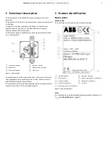
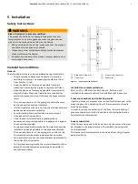
1
Stop valve in the inlet
2
Flowmeter
3
Stop valve in the outlet
4
Bypass line
Figure 4: Installation of the flowmeter
Installation recommendations
Refer to VDI / VDE Directive 3513 sheet 3, Selection and
Installation Recommendations for Variable Area Flowmeters.
Pressure chambers and collecting tanks
If piston pumps or compressors are used for the transport of the
measuring media, a pulsating flow of the measurement media
must be expected.
In order to reduce the pulsating of the float, the installation of
pressure chambers or collecting tanks in the piping before the
flowmeter is recommended.
Sensor insulation
If the flowmeter needs to be insulated, only the meter tube must
be included in the pipe insulation. The indicator housing must
not be insulated.
This prevents the temperature in the device from rising beyond
permitted limits.


