46 Electrical design and installation
Manual Energy Storage Inverter ESI-S
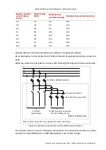
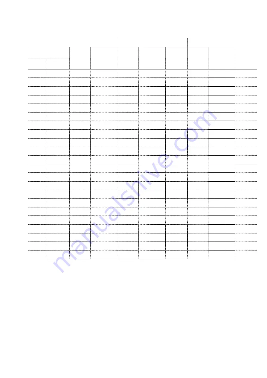
Table 21: Allowed cable current for different cable sections noting the skin effect
and typical cable manufacturer data – Network frequency 60Hz
Copper
Aluminum
Cross section
Nr of
parallel
cables
Derating
due to
paralleling
Rated
current
[Arms]
Reduction
factor
Allowed
current
[Arms]
Rated
current
[Arms]
Reduction
factor
Allowed
current
[Arms]
[mm²] [AWG]
16
6
1
1
100 0.996 99 75 1
75
25
4
1
1
130 0.99 128 100 1
100
35
2
1
1
160 0.981 157 120 0.99 119
50 1-1/0 1
1
190 0.965 183 145 0.98 143
70 2/0 1
1
230 0.941 216 180 0.97 175
95
3/0
1
1
285 0.911 260 220 0.95 210
120 4/0 1
1
325 0.88 286 250 0.93 233
150 300MCM 1
1
365 0.85 310 285 0.91 260
185 350MCM 1
1
415 0.817 339 325 0.89 288
240 500MCM 1
1
495 0.775 383 385 0.85 326
300 600MCM 1
1
550 0.738 406 425 0.81 346
16
6
2 0.8
160 0.996 159 120 1
120
25
4
2 0.8
208 0.99 205 160 1
160
35
2
2 0.8
256 0.981 250 192 0.99 190
50 1-1/0 2 0.8
304 0.965 293 232 0.98 228
70
2/0 2 0.8
368 0.941 346 288 0.97 280
95
3/0 2 0.8
456 0.911 415 352 0.95 336
120
4/0 2 0.8
520 0.88 457 400 0.93 374
150 300MCM 2 0.8
584 0.85 496 456 0.91 416
185 350MCM
2
0.8
664 0.817 542 520 0.89 460
240 500MCM 2 0.8
792 0.775 613 616 0.85 522
300 600MCM 2 0.8
880 0.738 649 680 0.81 553
Remark: The highlighted values in
refer to cable sizes that correspond to typical
inverter ratings. Note that in 4-wire systems, the neutral may have to carry up to 3 times
the line current rating of the inverter.
6.7 Selection of the power cable protection/inverter input protection
scheme
Once the power cables have been selected, a suitable cable and equipment protection
has to be selected. The protection only needs to protect the phases and not the neutral.
It is recommended to use fuses of type gG/gL with the RMS current ratings given in

