background image

ABB i-bus

£

 KNX 

Device technology 

© 2010 ABB STOTZ-KONTAKT GmbH 


11 

2.6

Manual operation 

General 

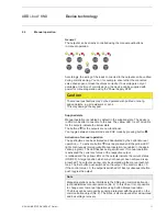
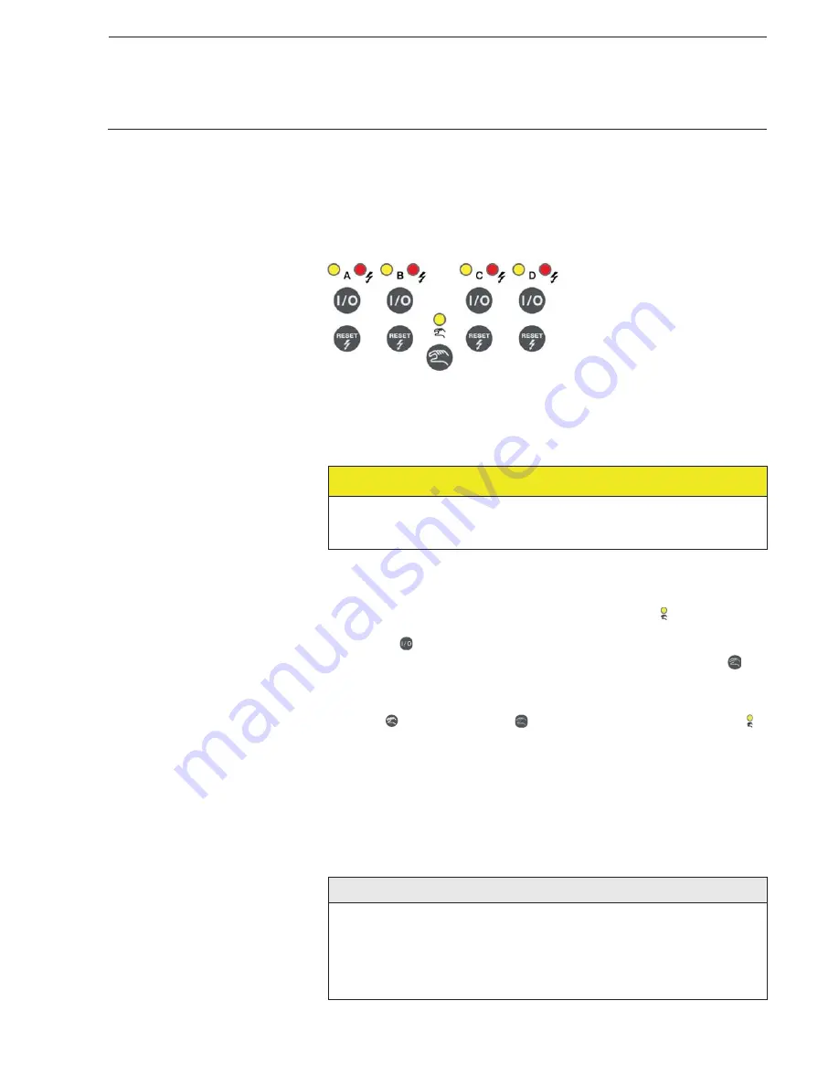
The outputs can be directly controlled using the manual pushbuttons  
in manual operation. 

Accordingly, the wiring of the loads connected to the outputs can be verified 
during commissioning. You can, for example, ensure that the connected 
valve drives open or close the valves correctly. If bus voltage is not yet 
available at the time of commissioning, the device can be supplied with 
power for manual operation using the Power Supply NTI/Z. 

Caution

The manual pushbuttons may not be operated with pointed or sharp-
edged objects, e.g. screwdrivers or pens.  
This may damage the keypad. 

Supplied state 

Manual operation is enabled by default in the supplied state. The device is  
in KNX mode after connection to the bus. The yellow LED   is off. All LEDs 
for the outputs indicate the actual state.  
The buttons 

 for the outputs are non-functional.  

You toggle between manual mode and KNX mode by pressing button 

.

Activation of manual operation 

The pushbuttons can be activated and deactivated by the button 

Manual

operation

. To activate, button 

 must be pressed until the yellow LED 

lights continuously (prerequisite: Manual operation is enabled in the appli-
cation program). The LED flashes during switchover. If manual operation 
is activated, the current set value of the respective output 
is retained and the yellow LEDs on the outputs indicate the current status 
(ON/OFF). A target position which may not have yet been achieved is ap-
proached. The outputs can now only be operated via the manual pushbut-
tons. The first button push switches on the output if the control value = 0.  
If the control value > 0, the output is switched off. Every subsequent button 
push toggles the output. 

Note 

Manual operation can be inhibited via the KNX using communication ob-
ject

 Enable/block manual operation

 (No. 2). In this case, it is not possible 

to change over to manual operation using button 

Manual operation

.

The block can be removed by sending a telegram with the value 0 on the 
communication object (No. 2). The block is also removed after a download 
and bus voltage recovery. 

Summary of Contents for ES/S 4.1.2.1

Page 1: ...ABB i bus KNX Electronic Switch Actuator ES S 4 1 2 1 Product Manual ...

Page 2: ......

Page 3: ...er window General 20 3 2 2 Parameter window Manual 23 3 2 3 Parameter window A General Selection Valve drive 26 3 2 4 Parameter window A Functions 32 3 2 4 1 Parameter window A Characteristic curve 37 3 3 Communication objects 40 3 3 1 Brief overview of the communication objects 40 3 3 2 Communication objects General 41 3 3 3 Communication objects Output A Operation mode Valve drive thermoelectric...

Page 4: ......

Page 5: ...n to the ABB i bus is established using the front side bus connection terminal The assignment of the physical addresses as well as the parameterization is carried out with Engineering Tool Software ETS from version ETS3 0f or higher 1 1 Using the product manual This manual provides you with detailed technical information relating to the function installation and programming of the ABB i bus KNX El...

Page 6: ...amming examples Important These safety instructions are used as soon as there is danger of a mal function without risk of damage or injury Caution These safety instructions are used if there is a danger of damage with in appropriate use Danger These safety instructions are used if there is a danger for life and limb with inappropriate use Danger These safety instructions are used if there is a dan...

Page 7: ...xample A B 230 V AC C D 24 V DC Rated current In per output 1 A resistive load at Tamb up to 45 C Inrush current per output 8 A for max 1 second at Tamb 20 C Number of thermoelectric valve drives per output The number of connectible valve drives per output is dependent on the maximum inrush current 8 A or continuous current 1 A of the output They may not be exceeded when several valve drives are c...

Page 8: ... required Weight Approx 0 2 kg Housing colour Plastic housing grey Approvals KNX to EN 50 090 1 2 Certification CE mark In accordance with the EMC guideline and low voltage guideline Application program Maximum number of communication objects Max number of group addresses Max number of associations Switching Valve Drive 4f 1A 1 2 48 254 254 Note ETS from version ETS3 0f or higher is required for p...

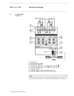
Page 9: ...3 Bus connection terminal 4 Button Manual operation and LED Manual operation 5 Button ON OFF and LED Status for every output 6 4 output terminals A D 7 2 terminals each L N for outputs A B C D 8 Button Reset and LED Fault for each output Note The outputs A B or C D can be operated with different mains voltage Un 2CDC 072 013 F0010 ...

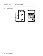
Page 10: ...ABB i bus KNX Device technology 2010 ABB STOTZ KONTAKT GmbH 8 2 4 Dimension drawing 2CDC 072 010 F0010 ...

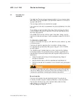
Page 11: ...ter connection to the bus voltage For supplying the connected load the mains voltage 24 230 V AC DC must be applied The installation and commissioning may only be carried out by qualified electrical specialists The appropriate norms guidelines regulations and specifications should be observed when planning and setting up electrical installations x Protect the device from damp dirt and damage durin...

Page 12: ...ress The assignment and programming of the physical address is carried out in the ETS The device features a button programming for assignment of the physical device address The red LED programming lights up after the button pro gramming has been pushed It switches off as soon as the ETS has as signed the physical address or the button programming is pressed again Cleaning If devices become dirty t...

Page 13: ... mode by pressing button Activation of manual operation The pushbuttons can be activated and deactivated by the button Manual operation To activate button must be pressed until the yellow LED lights continuously prerequisite Manual operation is enabled in the appli cation program The LED flashes during switchover If manual operation is activated the current set value of the respective output is re...

Page 14: ...s the highest priority Active functions e g blocking forced operation and purging are interrupted and values of the characteristic correction curve are not considered when the orginial state is changed in the manual operation using the button Manual operation is inactive after bus voltage recovery download or reset ...

Page 15: ...e only in KNX mode For resetting a fault short circuit or overload on the output provided that the fault has been rectified beforehand The Reset button must be pushed until the red LED switches off for this purpose A short circuit or an overload block the output until the fault is rectified and reset with the Reset button Continuous on Supply voltage absent The LED switches off as soon as the supp...

Page 16: ......

Page 17: ...r the conver sion program can still be useful to transfer the parameterization settings and group addresses of one device to another of the same type 3 1 1 1 Procedure x Import the current VD3 file into ETS3 and add a product with the current application program to the project x After you have parameterized a device you can transfer the settings to a second device For this purpose the devices must...

Page 18: ...requently controlled in an identical manner In this case the parameter settings from input output X can be copied to all other inputs outputs or to a special input output of the device Thus the pa rameters for this input output must not be set separately which significantly shortens the commissioning time The exchange of parameter settings is useful e g should the inputs outputs be swapped when wi...

Page 19: ...esign of the application so that parameter settings and group addresses can only be copied or exchanged in pairs Target channels With the selection of the target channels you define which channel channels are to assume the parameter settings of the source channel x For the function Exchange only one target output pair e g output CD can be selected at a time x For the function Copy different target...

Page 20: ...nel With this button you copy the settings of the source channel into the target channel or channels Exchange The following options can be selected before exchanging the parameter set tings x Retain group addresses x Exchange group addresses x Deleten group addresses With this button exchange the settings of the source channel with the target channel Confirm your selection with this button and the...

Page 21: ...ing Electronic Switch Actuator The following chapter describes the parameters of the ES S 4 1 2 1 using the parameter windows The parameter window features a dynamic struc ture so that further parameters or communication objects may be enabled depending on the parameterization and the function of the outputs The default values of the parameters are underlined e g Options yes no Note However as the...

Page 22: ... can be monitored by an external device If a telegram is not received the device may be defec tive or the bus cable to the transmitting device may be interrupted Notes After bus voltage recovery the communication object is sent after the set sending and switching delay x no The communication object In operation is not enabled x send value 0 1 cyclically The communication object In Operation is sen...

Page 23: ... has been completed An initialisation time of about two seconds is included in the delay time The initialisation time is the time that the processor requires to be functional How does the device behave with bus voltage recovery After bus voltage recovery the device always waits for the sending delay time to elapse before sending telegrams on the bus Limit number of telegrams Options no yes The loa...

Page 24: ...on always and after a change or request If a telegram with the value 0 or 1 depending on the parameterization is received on this communica tion object the Status bytes page 48 of the outputs are also sent x yes The 1 bit communication object Request status values page 41 is displayed An additional parameter is displayed Request with object value Options 0 1 0 or 1 x 0 Sending status messages is r...

Page 25: ... operating states man ual operation and KNX operation is enabled or disabled via the button on the device x enable disable via communication object The communication object Enable block manual operation page 41 is displayed Manual operation can be enabled or disabled via the bus with this communication object Telegram value 0 button enabled 1 button disabled x enabled With this selection the outpu...

Page 26: ...l operation remains activated after the last operation of the button until the parameterized time has timed out or it is deactivated again using the manual operation button Enable communication object Status man operation 1 bit Options no yes x yes The parameters Send object values and the communica tion object Status man operation page 42 appears Send object value Options no update only after a c...

Page 27: ...even if power saving mode has been activated The fault can be reset using the button Reset even if manual operation is inhibited When any button is pressed the power saving mode is interrupted and the status of the outputs is shown even if manual operation is inhibited If no other button is pressed the power saving mode is reactivated after the parameterized time and the LEDs switch off x after 1 ...

Page 28: ... thermoelectric mode has been selected Note However as the functions for all outputs are identical only the functions of output A will be described Operation mode Options none Valve drive thermoelectric x none The output is deactivated with this selection Note The outputs can however be operated via the manual pushbuttons in the default delivery state After the first download the outputs for which...

Page 29: ... current flows in the valve drive the valve opens De energised opened valve drives NO If no current flows in the valve drive the valve opens If current flows in the valve drive the valve then closes Reaction on bus voltage failure Options unchanged select Using this parameter the reaction of the output at bus voltage failure is set x unchanged The output and the valve drive remain in the same posi...

Page 30: ...This additional time extends the switch on and off duration after a change in the control value Accordingly the new control value is achieved quickly Reaction after bus voltage recovery Options unchanged select Using this parameter the reaction of the output at bus voltage recovery is set x unchanged The last control value received before bus voltage failure is set This also applies if a function ...

Page 31: ...ime of 15 mi nutes for example will be recalculated for a switch on duration of three minutes The control value 50 results in a switch on duration of 7 5 minutes Using pulse width modulation a relatively exact control of the temperature can be achieved without high levels of overshoot Simple attractively priced thermoelectric valve drives can be used x 1 byte The control value is sent by the therm...

Page 32: ...Options 10 180 6 000 Using this parameter the time which the connected valve drive requires for a complete motion from closed 0 to fully opened 100 is set Closing time of valve drive in s 10 6 000 Options 10 180 6 000 Using this parameter the time which the connected valve drive requires for a complete motion from opened 100 to fully closed 0 is set Note The closing and opening times should be tak...

Page 33: ...a setting variable is not received within the parameterized time a malfunction or a defective thermostat is the cause The reaction of the output to a control value not received can be de fined in the following parameters Send object value Object Fault control value 1 bit Options no update only after a change after request after a change or request x no update only The status is updated but not sen...

Page 34: ...k on object value Options 1 0 Here you set the value of the communication object used to block the output Enable communication object Forced operation 1 bit Options no yes x yes The 1 bit communication object Forced operation page 46 is en abled Using forced operation the operation of the output is inhibited and the output assumes a defined state With option yes the following parameters become vis...

Page 35: ...t is sent via this communication object x 1 bit The communication object Status control value page 47 1 bit and the following parameters are displayed Send object value Options no update only after a change after request after a change or request x no update only The status is updated but not sent x after a change The status is sent after a change x after request The status is sent after a request...

Page 36: ... period of valve purge the valve purge will no longer be executed after the higher priority has been rescinded The control for valve purging is always the control value 100 A correspondingly matched correction curve is taken into consideration With option yes the following parameters become visible Enable communication object Status valve purge 1 bit Options no yes The status of the valve purge is...

Page 37: ...er starts directly after a download The time is reset each time it is downloaded The time is reset as soon as purging is completed This can oc cur either through automatic purging or via the communication object Trigger valve purge Note Purging can also be triggered via the bus using the commu nication object Trigger valve purge After bus voltage recovery and download the automatic purging cycle i...

Page 38: ... here The entry of the opening time for the valve drive must be considered when entering the period for valve purge The purging cycle with an active automatic valve purge is reset and restarted if x A manual valve purge is triggered via the communication object Trigger valve purge x A parameterized value is received on the communication object Control value Reset purge cycle from control value in ...

Page 39: ...edge in heating air conditioning and ventila tion systems is a prerequisite The following must be considered with the characteristic curve correction x The value pairs can be entered in any sequence They are sorted in as cending order of the control value in the device and intermediate values are interpolated x If no value pair is assigned to the control value 0 the first value pair is always appl...

Page 40: ...his fact must be considered during parameteization Example Value pair 1 VP1 Value pair 2 VP2 Control value in 0 100 10 Control value in 0 100 80 Control in 0 100 40 Control in 0 100 20 Implemented characteristic curve correction Control value Control 0 10 40 20 37 30 34 40 31 50 29 60 26 70 23 80 100 20 100 WP1 WP2 40 10 80 Control Value in 20 Control in ...

Page 41: ...ibility of activating other value pairs allows different curve charac teristics to be realised A total of four value pairs can be set Enable value pair 3 Options no yes x yes Value pair 4 appears Value pair 3 Control value in 0 100 Options 0 50 100 Control value in 0 100 Options 0 50 100 Enable value pair 4 Options no yes x yes Value pair 4 appears Value pair 4 Control value in 0 100 Options 0 50 ...

Page 42: ...short circuit Output A DPT 1 005 1 bit x x x 12 Reset error message Output A DPT 1 005 1 bit x x x 13 Mains voltage failure Output A DPT 1 001 1 bit x x x 15 Fault control value Output A DPT 1 005 1 bit x x x 16 Trigger valve purge Output A DPT 1 017 1 bit x x 17 Status valve purge Output A DPT 1 003 1 bit x x x 18 Block Output A DPT 1 003 1 bit x x 19 Forced operation Output A DPT 1 003 1 bit x x...

Page 43: ...rameterization is received on the communication object for all outputs the status byte is sent as well as all other status values or communication objects programmed with the option after request or after a change or request x Status manual Operation x Fault control value x Status control value x Status valve purge Telegram value 1 0 Request status values 2 Enable block manual ope ration General 1...

Page 44: ...ice is controlled via the bus The status is sent if a request is received via the communication object Request status values and the parameter after request or after a change or request is present the value of the communication object has changed and the parameter after a change or after change or request is present a read request is carried out on this communication object Telegram value 0 manual...

Page 45: ...ontrol 1 bit The ES S receives the ON or OFF telegrams from the thermostat Telegram value 0 OFF 1 ON 10 Control value continuous PWM 1 byte Output A 1 byte DPT 5 001 C W This communication object is always displayed Using the parameter Control will be received as in parameter window A General page 26 control can toggle between 1 bit and 1 byte control 1 byte The communication object value 0 255 de...

Page 46: ...t on output A 12 Reset error message Output A 1 bit DPT 1 015 C W T Using this communication object an error message such as an Overload short circuit red Error LED flashing on the device is reset A reset is only successful after an error has been rectified and is no longer present The red Error LED switches off after a successful reset There is no reaction should the value 1 be received during co...

Page 47: ...s triggered using this communication object Telegram value 0 end valve purge valve is closed 1 start valve purge valve is opened The purging cycle time is restarted if automatic valve purge has been activated at start up of the device The purging cycle time will be restarted at the end of the actual purging period The param eterized valve purging duration is included here If the valve purge curren...

Page 48: ... 18 Block Output A 1 bit DPT 1 003 C W The output is inhibited blocked and the current control value is retained via this communica tion object Blocking of the output is implemented in accordance with the Priorities page 52 Implementation of a control value that may not have yet been achieved will be completed Telegrams are still received during the block The telegram last received is carried out ...

Page 49: ... parameter window General under parameter Control value is received as the option 1 bit is selected the following applies for the communication object Status control value 1 byte Telegram value 0 control value 0 control equal to zero LED yellow off 255 control value 1 control not equal to zero LED yellow on 21 Status control value 1 bit Output A 1 bit DPT 1 011 C R T This communication object is e...

Page 50: ...trol value 0 Telegram value 0 Control value 0 Telegram value 1 Control value 0 Bit 1 Short circuit Telegram value 0 No short circuit Telegram value 1 Short circuit Bit 2 Overcurrent 1 A Telegram value 0 No overcurrent Telegram value 1 Overcurrent Bit 3 Not used Bit 4 Mains voltage failure Telegram value 0 No failure Telegram value 1 Failure Bit 5 Manual operation active Telegram value 0 Manual ope...

Page 51: ...active at bus voltage recovery x A bus voltage failure 5 seconds is a reset and does not lead to defined behaviour after bus voltage recovery x Forced operation is re established and executed as a priority All other priorities e g blocking and valve purge are reset Control of valve drives x The purge cycle restarts if activated x The value parameterized for bus voltage recovery is set with the con...

Page 52: ...t be restarted Status values of the control values are updated and sent Note After a download with a change the parameter complies in behaviour toa reset of the device in the ETS If a download of the application is again undertaken full download after a full discharge the behaviour is the same as after a reset After the application is removed or after an interrupted download manual operation no lo...

Page 53: ... Block Blocking is ended Pa rameterized default posi tion is set with bus voltage failure Inactive communication object value is reset Inactive communication object value is reset Inactive communication object value is reset Valve purge Valve purge is ended Parameterized default position is set with bus voltage failure Valve purge is inactive Communication object Status valve purge 0 Injection cyc...

Page 54: ... The priorities for telegram processing are defined as follow 1 Overload short circuit 2 Bus voltage failure recovery 3 Manual operation 4 Block 5 Forced operation 6 Valve purge 7 Control value after control fault 8 Control values 1 bit 1 byte Note 1 corresponds to the highest priority ...

Page 55: ...ronic Switch Actuator is supplied together with the following com ponents Please check the items received using the following list x 1 x ES S 4 1 2 1 Electronic Switch Actuator 4 fold 1A MDRC x 1 x installation and operating instructions x 1 x bus connection terminal red black x 1 x label carrier ...

Page 56: ...6C 194 C2 23 17 109 6D 195 C3 24 18 110 6E 196 C4 25 19 111 6F 197 C5 26 1A 112 70 198 C6 27 1B 113 71 199 C7 28 1C 114 72 200 C8 29 1D 115 73 201 C9 30 1E 116 74 202 CA 31 1F 117 75 203 CB 32 20 118 76 204 CC 33 21 119 77 205 CD 34 22 120 78 206 CE 35 23 121 79 207 CF 36 24 122 7A 208 D0 37 25 123 7B 209 D1 38 26 124 7C 210 D2 39 27 125 7D 211 D3 40 28 126 7E 212 D4 41 29 127 7F 213 D5 42 2A 128 ...

Page 57: ...moelectric Valve Drive 230 V Normally Closed 2CDG 110 007 R0011 65299 5 20 0 1 1 TSA K 230 1 Thermoelectric Valve Drive 24 V Normally Closed 2CDG 110 008 R0011 65300 8 20 0 1 1 VA Z 10 1 Valve Adapter M30 x 1 5 for Dumser Chronatherm Vescal KaMo 2CDG 110 009 R0011 65319 0 20 0 01 1 VA Z 50 1 Valve Adapter M30 x 1 5 for Honeywell Reich Cazzaniga Landis Gyr MNG 2CDG 110 010 R0011 65320 6 20 0 01 1 V...

Page 58: ...ABB i bus KNX Appendix 2010 ABB STOTZ KONTAKT GmbH 56 A 5 Notes ...

Page 59: ......

Page 60: ...nts of this document without prior notice With regard to purchase orders the agreed particulars shall prevail ABB AG does not accept any responsibility whatever for potential errors or possible lack of information in this document We reserve all rights to this document and in the subject matter and illustrations contained therein Any reproduction disclosure to third parties or utilization of its c...

Reviews: