Endura APA592
pH / Redox (ORP) transmitter
4 Electrical Installation
OI/APA592–EN Rev. E
29
4.3 Sensor Connections
To connect the sensor:
1.
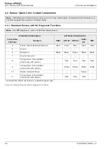
Refer to Tables 4.2 and 4.3 on pages 30 and 31 to identify the correct cable wires / colors for the
APA592–PH transmitter.
2.
Route the sensor wiring through one of the three threaded connections and use an appropriate
gland in the transmitter housing (refer to Fig. 4.1, page 27 for gland options). Note, a cable gland is
required.
3.
Loosen the sensor connection terminal captive screws using a flat-bladed screwdriver (3.5 / 4 mm or
Size-1).
4.
Insert each sensor cable wire under the open terminals and secure by tightening the terminal captive
screws.
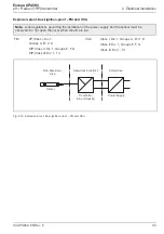
Fig. 4.3 APA592–PH Sensor Connections at Transmitter Terminals
Caution.
The connection terminals accept cables up to a maximum peripheral wire cross section of
2.5 mm
2
(12 SWG [10 AWG]).
If possible use coaxial cable
(do not use a rigid conductor material as this can result in wire breaks).
Ensure the connecting cable is flexible.
To ensure the sensor cable length is sufficient, allow an additional 100 mm (4 in.) of cable to pass
through cable glands and into the housing.
Ensure the correct connections are made to suit the sensor model (see Section 4.4, page 30).
10
Key
:
4
Sense
5
Guard
6
Ref
7
Sol Gnd
8
RTD 1
9
RTD 2
0
Shield
k
RTD 3
Connection Label
(inside End Cap)


