9
8. Mounting
Install the electronic unit outside the hazardous area. Connect the actuator and the electronic unit via
the screw associated screw terminals. The electronic units are provided with the appropriate metric ca-
ble holes (see Figures 1 to 3 for the assignment).
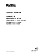
Fig. 7:
Arrangement of the components
8.1
Preparing the electronics
-
Make sure that disconnection on site is possible.
-
Shield all signal cables and the motor cable between the actuator and the electronics
-
The shield of the connection cable between the electronics and the actuator must be applied to both
housings.
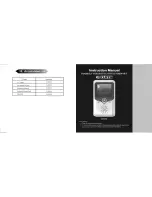
8.2
EBN853
Disconnect the electronic unit and the actuator prior to all installation and service works.
-
Fasten the unit to the vertical mounting plate, using screws of property class 8.8 (tensile strength
800 N/mm
2
; yield strength 640 N/mm
2
)
-
Make sure that there is enough spacing for mounting, and that the unit can be easily accessed
-
Make sure that the cable holes are oriented to the left
-
Remove the cover of the connection chamber (2)
-
Insert the cables through the cable glands and connect them according to the wiring diagram.
-
Use appropriate cable glands to ensure a water-tight installation
-
Check if the cable is connected properly; then close the connection chamber cover.
ϑ
Contrac electronic unit
motor temperature
(e. g. SD241B)
nonEx area
hazardous area
ex classification:
Contrac actuator
position sensor
DCS / controller
AC 115 / 230 V 1~
temperature
motor /
brake wire
(screened)
sensor connection chamber
sensor electronics
(anticondensation heater optional)
Bremse
motor with
temperature
sensor wire
(screened)
signal cable from / to
DSC / controller
(screened)
motor
connection
r00376x1
wire
II 2 GD ck EEx de [ib] ib II B T4 bzw
IP6x T=130°C
monitoring unit
sensor
sensor
chamber