


EL3000
CONTINUOUS GAS ANALYZERS | OI/EL3000-EN REV. D
143
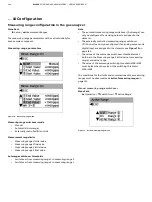
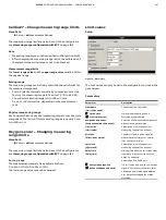
Measuring range limits and autorange switching thresholds
The lower range values and upper range values as well as the
autorange switching thresholds are configured in the
‘Measurement Range’ measuring range limit dialog:
Figure 74: ‘Measurement Range’ menu
Note
• The values of the autorange switchover thresholds must
both be in the ‘Measuring range 2 initial value to measuring
range 1 end value’ range.
• The value of the autorange switching threshold MR2->MR1
must be less than the value of the switching threshold
MR1->MR2.
The conditions for the limits and combinations of the measuring
ranges must be observed, see
page 141.
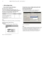
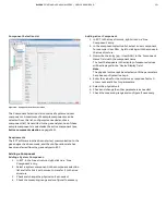
Configuration of inputs and outputs for measuring
range switchover and feedback
Figure 75: ‘IO Connections’ menu
In the example shown in the figure, the following inputs and
outputs are assigned to the Uras26 detector 1 (see yellow
marking):
• the X20-AO1 analog output for the measured value output
(‘Iout’),
• the X22-DI4 digital input for external control of the
measuring range switchover (‘MR Control’),
• The X22-DO4 digital output for the measuring range
feedback (“MR Feedback“).
Functionality of digital inputs and outputs for measuring
range switchover and feedback
Active measuring
range
Switching
state*
Digital input**
Digital output**
Measuring range 1 0
open Relays de-energized
Measuring range 2 1
closed
Relays energized
* Inputs and outputs are not inverted
** For possible wiring of the inputs and outputs see
on
page 97


