


Voltage
Monitors
7.4
Low Voltage Products & Systems
1TRC 001 009 C0202
ABB Inc. • 888-385-1221 • Technical assistance 800-377-7722 • www.ssac.com
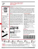
Description
The WVM Series provides protection against premature equipment (motor) failure caused by voltage faults on
the 3 Phase Line. The WVM’s microcontroller design provides reliable protection even if regenerated voltages
are present. It combines dependable fault sensing with a 10 fault memory and a 6 LED status display. Part
instrument, part control, the WVM protects your equipment when you’re not there and displays what happened
when you return. The WVM is fully adjustable and includes time delays to prevent nuisance tripping and
improve system operation. Time delays include a 0.25 to 30 s adjustable trip delay, an adjustable 0.25 to 64
m (in 3 ranges) restart delay, plus a unique 3 to 15 s true random start delay. The random start delay prevents
voltage sags caused by simultaneous restarting of numerous motor loads after a power outage.
Operation
The output relay is energized when all conditions
are acceptable and the WVM is reset. A restart
and/or random start delay may occur before the
output relay is energized.
Protects Against: Phase
Loss & Reversal; Over,
Under & Unbalanced
Voltages; Short Cycling
10 Fault Memory & Status
Displayed on 6 LED Readout
Switch Selectable Automatic
Restart, Delayed Automatic
Restart, & Manual Reset
Isolated 10 A SPDT Relay
Contacts
Approvals:
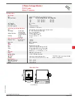
3 Phase Voltage Monitor
WVM Series
Motor Protector
Example P/Ns:
WVM
X
–
6
- 200 ... 240 V AC
–
8
- 355 ... 425 V AC
–
9
- 400 ... 480 V AC
–
0
- 500 ... 600 V AC
3 Phase Line Voltage
X
–
1
- 2 ... 10%
X
–
1
- 0.25 ... 30 s
Unbalance Trip Delay
X
–
A
- Switch Selectable:
Automatic Restart Upon Fault Trip
–
R
- Switch Selectable:
Automatic Restart Upon Fault
Correction
X
–
L
- 0.25 ... 64 s
–
N
- 6 ... 300 s
–
H
- 0.25 ... 64 m
Reset Method
Restart Delay
WVM011AL,
WVM911AL-60
(No Random Restart Delay)
Field Adjustment:
Select the line voltage listed
on the motor’s name plate. This automatically sets
the over and under voltage trip points. Consult the
equipment’s manufacturer specifications for the
correct trip delay, unbalance percentage, and restart/
reset operation and restart delay. Make connection
to all three line phases as shown in the connection
diagram. Apply power. If the relay fails to energize,
view the LEDs for the cause, and correct the problem.
If the phase sequence is incorrect, swap any two
wires. No further adjustment should be required to
achieve maximum equipment protection.
Read Memory:
Fault(s) stored in the memory
are indicated when the yellow LED is flashing. To
read memory, rotate selector from Manual to Read
Memory. The last fault will be displayed. Repeat this
operation to read the second to the last fault. Repeat
until up to 10 faults are noted.
Memory Reset:
To clear the memory of all
faults stored, rotate selector to Clear Memory
for 5 seconds. The yellow LED will turn off.
Memory Overload:
The 11th fault causes the
first to be removed from memory. Only the 10
most recent faults are retained.
Random Start Delay:
A new 3 to 15 s random start
delay is selected by the microcontroller when a fault
is corrected and when the operating voltage (L1, L2,
L3) is applied to the WVM. A random start delay does
not occur when the reset is manual.
Automatic Restart:
Upon fault correction, the output
will re-energize after a random start delay.
Automatic Restart Upon Fault Trip:
When a fault is
sensed for the full trip delay, the output de- energizes
and a restart delay is initiated. This delay locks out
the output for the delay period. Should the fault be
corrected by the end of the restart delay, the output
will re-energize after a random start delay. A restart
delay will also occur when operating voltage (L1, L2,
L3) is applied to the WVM.
Manual Reset:
After a fault condition is corrected,
the WVM can be manually reset. There are two
methods; a customer supplied remote switch, or the
onboard selector switch.
Manual Reset (Onboard):
Rotate selector switch
from the Manual Reset position to Auto Restart
w/ Delay then back again to Manual Reset within 3
seconds. The output will immediately energize.
Remote Reset:
Reset (Restart) is accomplished
by a momentary contact closure across terminals 1
& 2. The output will immediately energize. Remote
switch requirements are
≥
10 mA at 20 V DC and the
reset terminals are not isolated from line voltage. A
resistance of
≤
20K
Ω
across terminals 1 & 2 will
cause immediate automatic restart.
Automatic Restart Upon Fault Correction:
(P/N includes an
R
)
When a fault is sensed for the full trip delay, the output
relay de-energizes. Upon correction of the fault, a
restart delay begins. At the end of this delay, the
output will re-energize after a random start delay. If
a fault occurs during restart timing, the restart time
delay will be reset to zero, and the output will not
energize until the restart delay is completed.
-60 Option: Add the suffix -60 to any automatic
restart part number to remove the Random Start
Delay feature. See example P/N‘s below.
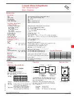
Connection
F = Fuses
NO = Normally Open
NC = Normally Closed
RS = Optional Remote Reset Switch
CAUTION:
2 amp max fast acting
fuses must be installed
externally in series with
each input. (3)
Series
Relay contacts are isolated.
Dashed lines are internal
connections.
ASME A17.1 rule 210.6
NEMA MG1 14:30, 14:35
IEEE C62.41-1991 Level B
ANSI Device #27/47/59
Listed
WVM02B01
12.13.06


