


Voltage
Monitors
7.22
Low Voltage Products & Systems
1TRC 001 009 C0202
ABB Inc. • 888-385-1221 • Technical assistance 800-377-7722 • www.ssac.com
X
–
2
- Onboard Adjustment
3...300 s
X
HLV
X
Series
–
4
-
70
... 120 VAC
–
6
- 170 ... 220 VAC
Undervoltage Range
Restart Delay
Trip Delay
– Fixed 1 ... 20 s in
1 s increments
X
Output Connection
Description
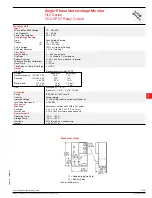
The HLV Series is a single phase undervoltage monitor designed to protect sensitive equipment from brownout
or undervoltage conditions. Time delays are included to prevent nuisance tripping and short cycling. The 30 A,
1 hp rated SPDT relay contacts allow direct control of motors, solenoids and valves. The output relay can be
ordered with isolated SPDT contact to allow monitoring of one voltage and switching a separate voltage. Two
undervoltage trip point ranges allow monitoring of 110 to 120 VAC or 208 to 240 VAC systems.
HL
V02B01
12.05.06
Protects against undervoltage
in Single Phase Systems
30 A SPDT N.O. Output
Contacts
100 ... 240 VAC Input Voltage
70 ... 220 VAC Adjustable
Undervoltage Trip Point in
2 Ranges
Restart Delays from 3 ... 300 s
Trip Delay 1 ... 20 s Fixed
Isolated or Non Isolated Relay
Contacts
Approvals:
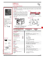
Single Phase Undervoltage Monitor
HLV Series
30 A SPDT Relay Output
Connection
Accessories
See accessory pages for
specifications.
Quick connect to
screw adaptor
P/N:
P1015-18
Female quick
connect P/Ns:
P1015-64
(AWG 14/16)
P1015-13
(AWG 10/12)
←
DIN rail adaptor
P/N:
P1023-20
→
N
= Relay contacts
are non-isolated.
Operation
Mounting bracket
P/N:
P1023-6
NO = Normally Open
NC = Normally Closed
C = Common
T1 = Undervoltage Trip Point
T2 = Restart Delay
US Patent 6708135
Dashed lines are internal
connections.
Upon application of input voltage the output relay re-
mains de-energized. When the input voltage value is
above the pull-in voltage, the restart delay begins. At
the end of the restart delay, the output relay energiz-
es. When the input voltage falls below the trip point,
the trip delay begins. If the input voltage remains
below the pull-in voltage for the entire trip delay the
relay de-energizes. If the input voltage returns to a
value above the pull-in voltage, during the trip delay,
the trip delay is reset and the relay remains energized.
If the input voltage falls below the trip point voltage
during the restart delay, the delay is reset and the
relay remains de-energized. Reset is automatic upon
correction of an undervoltage fault.
Reset:
Removing input voltage resets the output
relay and the time delays.
–
I
= Isolated SPDT
–
N
= Non-Isolated
SPDT
Example P/N’s:
HLVA4N25
= 70 ... 120 VAC Trip Point Range, Non-Isolated SPDT, Adjustable Restart Delay, Trip Delay fixed at 5 seconds
HLVA6I220
=170 ... 220 V Trip Point Range, Isolated SPDT, Adjustable Restart Delay, Trip Delay fixed at 20 seconds
Dashed lines are internal
connections.
I
= Relay contacts are
isolated.
PI
TP
V
C-NO
C-NC
IV
tr = Restart Delay
td = Trip Delay
PI = Pull-in 105% or trip point
TP = Trip Point
V = Monitored Voltage
IV = Input voltage
C-NO = Normally Open Contacts
C-NC = Normally Closed Contacts
Function
A
DIN rail P/Ns:
017322005
(Steel)
C103PM
(Al)


