48
Electromagnetic Flowmeter
COPA-XE / MAG-XE
9.3.4
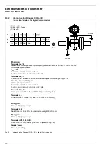
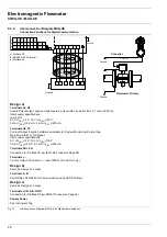
Interconnection Diagram MAG-XE
Connection Variations for Digital Communication
Design a)
Terminals Ux, V8
Scaled Pulse Output, passive (Optocoupler), pulse width can be set from 0.1 ms to 2000 ms,
Optocoupler specifications:
f
max
5 kHz
0 V
≤
U
CEL
≤
2 V, 16 V
≤
U
CEH
≤
30 V;
0 mA
≤
I
CEH
≤
0.2 mA, 2 mA
≤
I
CEL
≤
220 mA
Terminals Ux, P7
Contact Output, Function software selectable for System Monitoring, Empty Pipe,
Max.-Min.-Alarm or F/R Signal
Optocoupler specifications:
0 V
≤
U
CEL
≤
2 V, 16 V
≤
U
CEH
≤
30 V;
0 mA
≤
I
CEH
≤
2 mA, 0.2 mA
≤
I
CEL
≤
220 mA
Terminals PA+, PA-
Connection for Profibus PA per IEC1158-2 (see also Page 50)
Ter, -
Current Output, Terminals: +/-, load
≤
600
Ω
(4 to 20 mA only)
Design b)
Same as Design a), except
Terminals A, B
Serial Data Link RS485 for Communication using ASCII-Protocol
Design c)
Same as Design a), except
TerVD, A, B, GND
Connection for Profibus DP per EN50170 (see also Page 49)
Supply Power
See Instrument Tag
L < 50 m
Ground
Ground
Converter
Flowmeter Primary
c) Profibus DP
b) RS485 (ASCII Protocol)
a) Profibus PA
b)
c)
a)
Ground
Ground
Fig. 37
Interconnection Diagram MAG-XE for Digital Communication
Summary of Contents for COPA-XE
Page 4: ......


