background image

38

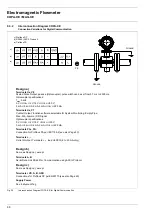
Electromagnetic Flowmeter

COPA-XE / MAG-XE

7.2

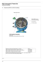
Replacement Parts List (Cable Assembly)

The Part No. for the cable assemblies includes the cables for the in- and outputs and include.
Crimp-Plug and the connection terminals (soldered) labeled.

Replacement Parts List, Cable Assemblies for In-/Outputs

Part No.

Cable assembly for standard outputs incl. HART (Versions 1-4)
Cable assembly for designs with RS 485 (ASCII Protocol) (Version 5)
Cable assembly for designs with Profibus DP (Version 6)
Cable assembly for designs with Profibus PA (Version 7)

D677A294U01
D677A294U04
D677A294U05
D677A294U06

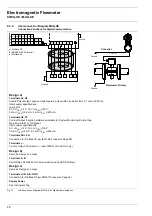
Cable Assembly for Connecting the
Converter Module and Terminal Strip
(In-/Outputs)
(There are various cable assembly versions, see Table)

Supply Power Cable

Cables Which Connect
to the Flowmeter Primary

a) Coil Excitation

b) Electrode Signal

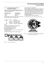
Fig. 19

Summary of Contents for COPA-XE

Page 1: ...E MAG XE Instruction Bulletin Electromagnetic Flowmeter with Pulsed DC Magnetic Field Excitation Model DE41 DE43 DE21 DE23 Valid for Software Versions B 11 and higher D184B105U02 Rev 01 05 2000 ABB Automation ...

Page 2: ...he right to make hardware and software improvements without prior notice Any questions which may arise that are not specifically answered by these instructions should be referred to our manufacturing plant in Göttingen Germany Tel 49 0551 905 0 or to the Service person responsible for your account Copyright by ABB Automation All Rights Reserved The interference resistance of this flowmeter system ...

Page 3: ...view of the Disposal Law of 27 Aug 86 AbfG 11 Special Wastes the owner of special wastes is responsible for its care and the employer also has according to the Hazardous Material Law of 01 Oct 86 GefStoffV 17 General Protection Responsibility a responsibility to protect his employees we must make note that a All flowmeter primaries and or flowmeter converters which are returned to ABB Automation P...

Page 4: ......

Page 5: ...eric entry 24 4 12 3 2 Unit Name Entry from table 24 4 12 3 3 Programmable Units Entry from table 24 4 13 Submenu Alarm Entry from table 25 4 13 1 Error Register 25 4 13 2 Setting the MAX Alarm 25 4 13 3 Setting the MIN Alarm 26 4 14 Submenu Prog In Output Entry from table 26 4 14 1 Contact Output Terminals P7 G2 Ux P7 for Profibus 26 4 14 1 1 General Alarm Errors 0 to 9 A B Entry from table 26 4 ...

Page 6: ... Parts List Cable Assembly 38 7 3 Replacement Parts for Flowmeter Primary 39 8 Accuracy 40 9 Safety Relevant Section of the Instruction Bulletin 41 9 1 Grounding the Flowmeter Primary 41 9 1 1 Grounding Models DE21_ and DE23_ 42 9 1 2 Grounding for Flowmeters with Hard or Soft Rubber Liners 42 9 2 Signal and Excitation Cable Connections for Model MAG XE 43 9 2 1 Signal and Excitation Cable Constru...

Page 7: ...k for correct coordination between the con verter and flowmeter primary The last digits of the flowme ter primary serial number as indicated on the Instrument Tag end in A1 A2 etc while the corresponding end charac ters for the converter end in B1 B2 etc A1 and B1 consti tute a single entity Compact Design COPA XE The µP Converter and the flowmeter primary constitute a single mechanical entity Alu...

Page 8: ...ing tube perpendicular to the direction of the magnetic field see schematic UE B D F The voltage induced in the fluid is measured by two electrodes located diametrically opposite to each other This signal voltage UE is proportional to the magnetic induction B the electrode spacing D and the average flow velocity v Noting that the magnetic induction B and the electrode spacing D are constant values...

Page 9: ...p within the meter Fig 2 Vertical installations are ideal when the fluid flows in an upward direction Installations in drop lines i e the fluid flows from the top to the bottom are to be avoided because experience has shown that it is not possible to guarantee that the pipeline will remain full and that an equilibrium condition between the upward flowing gas and the downward flowing liquid will no...

Page 10: ...m section of 2 x D are sufficient D flowmeter primary size Fig 7 In calibration stands the reference conditions of EN 29104 require straight lengths of 10 x D upstream and 5 x D downstream Wafer valves are to be installed in such a manner that the wafer when open does not extend into the flowmeter Valves or other shut off devices should be installed downstream A µP converter option offers an autom...

Page 11: ...unting bolts are to be tightened equally in the usual manner without excessive one sided tightening We recom mend that the bolts be greased prior to tightening and that they be tightened in a criss cross pattern as shown in Fig 10 Tighten the bolts during the first pass to approx 50 during the second pass to approx 80 and only during the third pass to 100 of the max torque value The max torque val...

Page 12: ...edure 1 Calculate the diameter ratio d D 2 Calculate the flow velocity as a function of the meter size and the flow rate The flow velocity can also be determined from the Flow Rate Nomograph 3 The pressure drop can be read on the Y axis at the intersection of the flow velocity value and the Diameter Ratio d D value on X axis in Fig 11 d EMF inside diameter D Pipeline inside diameter v Flow velocit...

Page 13: ...40 40 40 0 to 1 5 l min 0 to 2 25 l min 0 to 5 0 l min 0 to 7 5 l min 0 to 30 l min 0 to 45 l min 0 to 100 l min 0 to 150 l min 1 25 1 1 4 32 1 1 2 40 40 40 40 0 to 10 l min 0 to 20 l min 0 to 30 l min 0 to 200 l min 0 to 400 l min 0 to 600 l min 2 50 2 1 2 65 3 80 40 40 40 0 to 3 m3 h 0 to 6 m3 h 0 to 9 m3 h 0 to 60 m3 h 0 to 120 m3 h 0 to 180 m3 h 4 100 5 125 6 150 16 16 16 0 to 12 m3 h 0 to 21 ...

Page 14: ...on is greater than 9 999 999 units the flow direction symbol F or R and the units e g m3 blink in the 2nd line A converter software counter can register a max of 250 overflows The overflow indication can be reset separately for each flow direction by pressing ENTER If an error is detected an error message is displayed in the 1st line This message is displayed alternately in clear text and then by ...

Page 15: ...sing is open the EMC Protection personnel contact protection and the Ex Protection are voided C CE The C CE key is used to toggle back and forth between the operating mode and the menus STEP The STEP key is one of two arrow keys STEP is used to scroll forward through the menus All desired parameters can be accessed DATA The DATA key is one of two arrow keys DATA is used to scroll backward through ...

Page 16: ...3 h Current Output Change Parameter Qmax ENTER Qmax Change Parameter Current Output ENTER Current Output m3 h 0 20 mA Change Current Output from 0 20 mA to 4 20 mA Current Output Qmax ENTER 0 20 mA 6 2 4 0 0 0 m3 h 6 x DATA 6 STEP Find desired current output range 4 20 mA in table 2 x DATA 2 STEP or DATA Current Output STEP 4 20 mA Enter the desired numbers in series 4 x DATA 4 STEP 0 STEP Accept ...

Page 17: ...the PP Code Enter old PP Code 0 Factory setting Enter new PP Code 0 255 from table German English French Finnish Spanish Italian Dutch Danish Swedish For HART Protocol only German English French Spanish Present meter size See Instrument Tag on flowmeter primary Automatic setting based on the flowmeter size selection Flow range end value can be set from 0 05 to 1 0 Qmax DN Flowmeter span value Cs f...

Page 18: ... Pulse width can be set between 0 1 ms and 2000 ms numeric Range 0 10 of the flow range setting applies to the display indication and all outputs If the flowrate is below the low flow cut off value the flowrate measurements are stopped numeric Range 0 5 99 9999 s Response time for the current output to reach 99 of a flowrate step change numeric On off Standard is off If the output signal is noisy ...

Page 19: ... A B C are stored The error register can be cleared by pressing ENTER Limit alarm range 0 130 of the flow range setting Can be set in steps of 1 switching hysteresis 1 Limit alarm range 0 130 of the flow range setting Can be set in steps of 1 switching hysteresis 1 from table Contact output Terminal P7 G2 selections for Profibus terminals Ux P7 General alarm empty pipe1 F R signal no function MAX ...

Page 20: ...e as fol lows This is for information purposes only There is no further parameter setting pos sible Instrument address is 126 Default Value The address can be changed by Profibus communication on the bus HART protocol communication available if meter with this option has been ordered With HART protocol communication the menu structure will be as follows This is for information purposes only There ...

Page 21: ...n see Sect 4 17 Automatically function test internal assemblies Test RAM ASIC NVRAM EPROM Program EEPROM ext EEPROM Also tests additional functions terminals P7 G2 switch S201 display terminals X1 G2 Simulation and Test Mode For additional information see Sect 4 17 from table numeric Off Detector turned off On When flowmeter is empty message displayed The following menus are visible when the Empty...

Page 22: ...er Difference totalizer forward and reverse flows are totalized and displayed as a single value from table Exit the submenu Selections for the 1st display line flow rate in direct reading engineering units mA totalizer totalizer forward totalizer reverse TAG Number or bargraph See 1st Line In addition to the values displayed in the 1st line it is possible to display another value in multiplex oper...

Page 23: ... in the external EEPROM is also available from table After start up the parameter settings should be stored in the external EEPROM Display of the software version being used 03 99 Date of the release B 10 Revision level An alphanumeric TAG number with up to 16 characters including upper and lower case letters can be entered to identify the meter location For HART Protocol the TAG Number is limited...

Page 24: ...18 Electromagnetic Flowmeter COPA XE MAG XE ...

Page 25: ...ues Fwd Rev 4 19 2 Totalizer Function 4 19 2 1 Totalizer Function Standard 4 19 2 2 Totalizer Function Difference Totalizer 4 20 Submenu Display 4 20 1 Display 1st Line 4 20 2 Display 2nd Line 4 20 3 1st Display Line Multiplex 4 20 4 2nd Display Line Multiplex 4 21 Submenu Operating Mode 4 21 1 Operating Mode Standard Fast 4 21 2 Flow Direction 4 21 3 Flow Direction Indicators 4 22 Load Data from ...

Page 26: ...eter primary size selected 4 4 Qmax Numeric entry The flow range end value Qmax applies to both flow directions The flow range end value can be set between 0 05 Qmax DN and 1 0 Qmax DN The selection is made with the STEP and DATA keys The units are selected in Submenu Units The values for the totalizer functions are checked based upon the selections for the pulse factor 0 01 to 1000 pulses unit th...

Page 27: ... small the following message is displayed 4 6 Pulse Width Numeric entries The pulse width length of the pulses of the scaled pulse output can be set in the range from 0 1 ms to 2000 ms For technical reasons the pulse width is always a multiple of 0 032 ms On the one hand the pulse width must small enough so that at the max output frequency flowrate max 130 5 kHz overlaps do not occur while on the ...

Page 28: ...and the low flow cutoff limit the flow is not integrated The current output is set to its zero value A 1 hysteresis is incorporated in the low flow cutoff limit 4 8 Damping Numeric entries The damping can be set in the range from 0 5 to 99 9999 s The entry refers to the response time for the output to reach 99 of its final value for a step change in the flowrate It is effective for the indicated v...

Page 29: ...justment is not completed The value determined by the converter is displayed in the 2nd line 4 12 Submenu Units The following parameters are included in this submenu Engineering Units Qmax Engineering Units Qmax Engineering units with Units Factor user programmable Unit Name user programmable and Prog Units with without density correction The last three entry parameters are required for any new us...

Page 30: ...rammable Units With this function it is possible to program any desired unit in the converter The following three parameters are included in the this function a Units factor b Unit name c Programmable units with without density Note Entering data in the parameters a b and c is only necessary if the desired direct reading engineering units are not listed in the table integrated in the converter 4 1...

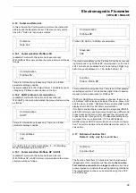
Page 31: ...r text description for each error code Error 0 Empty pipe Error 8 negative reference voltage too large Exit the help text information by pressing C CE 4 13 2 Setting the MAX Alarm The limits for the desired MAX Alarm value can be set in 1 steps from 0 to 130 This value applies to both the forward and reverse flow directions When MAX Alarm is selected the contact is actuated when the flowrate excee...

Page 32: ...t available and the output functions are assigned to terminals Ux P7 4 14 1 Contact Output Terminals P7 G2 Ux P7 for Profibus The functions which can be assigned to the output contact terminals P7 G2 are listed below General alarm Errors 0 9 A B 4 14 1 1 Empty pipe 4 14 1 2 F R direction signal 4 14 1 3 No function 4 14 1 4 MAX Alarm 4 14 1 5 MIN Alarm 4 14 1 6 MAX MIN Alarm 4 14 1 7 Warning Can b...

Page 33: ...e flowrate is greater than the MAX Alarm value or less than the MIN Alarm value In this mode it is also possible to indicate when the flowrate is within the two limit values set in MIN and MAX Alarm In this configuration the MAX Alarm value must be set smaller than the MIN Alarm value When the flowrate is within this range a signal is indicated in the display and on the terminals P7 G2 Ux P7 for P...

Page 34: ...us DP Communication even though this menu is displayed it has no function because a current output is not available 4 15 1 Current Output Range Entry from table The current output ranges listed below can be selected using the STEP and DATA keys For HART Protocol the current output range is fixed at 4 20 mA and cannot be changed Current Output 0 20 mA 4 20 mA 0 10 mA 2 10 mA 0 5 mA 0 10 10 20 mA 4 ...

Page 35: ...The instrument address has to be set using 3 digits e g 065 Range of addresses 0 126 Default Value 126 This is information purposes only There is no further parame ter settings possible For detailed description refer to special manual data link description for Profibus DP If ASCII or ASCII2w communication is choosen the menu in str Address will be displayed instead of the menu Slave Adr and the me...

Page 36: ... the letters A to F in the 1st and 2nd lines of the display Visually monitor for proper operation of the dot matrix Terminal X1 Select External Zero Return and press ENTER Apply a 24 V DC voltage to terminals X1 and G2 Plus polarity to X1 The converter indicates off on Terminal X1 Select Totalizer Reset and press ENTER Apply a 24 V DC voltage to terminals X1 and G2 Plus polarity to X1 The converte...

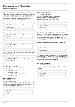
Page 37: ... to adjust the value to 2000 Hz 25 Hz Accept this value by pressing ENTER Empty the pipeline The adjustment value must increase above 2300 Hz Threshold Note To assure proper operation of the function Empty Pipe Detector the fluid conductivity must be at least 20 µS cm and the minimum meter size 3 8 DN 10 4 19 Submenu Totalizer The following functions are included in this submenu Reset totalizer an...

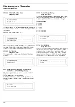
Page 38: ...d totalizer and difference totalizer 4 19 2 1 Totalizer Function Standard When Totalizer Function Standard is selected the totalizer pulses for the forward and reverse flow directions are counted independently on two totalizers When the flow direction is forward only the forward totalizer integrates the flow The selection is made with the STEP and DATA keys and accepted by pressing ENTER 4 19 2 2 ...

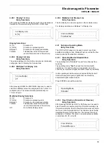
Page 39: ...the multiplex mode For display selections see Multiplex 1st Display Line 4 21 Submenu Operating Mode Entry from table The STEP or DATA keys can be used to select one of two available operating modes Standard Fast as well as the flow direction and the flow direction indication 4 21 1 Operating Modes Standard Fast Entry from table The operating mode Standard is used for continuous flow metering The ...

Page 40: ...ted Call the parameter and initiate the procedure by pressing ENTER 4 24 Software Version The Model Number of the converter is displayed in the 1st line while in the 2nd line the part number of the software is displayed These parameters cannot be changed An example of a display is shown 3 99 Release date B10 Revision level 4 25 TAG Number Instrument Address for Profibus Communication Numeric entry...

Page 41: ... 99 Instrument Address Reduce entry value Increase entry value as a function of the excitation frequency Reduce entry value 38 39 40 41 Entry 1000 Pulses Unit Entry 0 001 Pulses Unit Max pulse frequency exceeded scaled pulse output Pulse factor 5 kHz Min pulse frequency below limit 0 00016 Hz Reduce entry value Increase entry value Reduce pulse factor Increase pulse factor 42 43 44 45 46 Entry 200...

Page 42: ...ersion 04 Current Output Pulse Output passive Contact Input Contact Output HART Protocol Version 05 Current Output Pulse Output passive Contact Output RS 485 Version 06 Pulse Output passive Contact Output Profibus DP Version 07 Current Output Pulse Output passive Contact Output Profibus PA Fuse A Part No For low voltage 1A D151B025U07 For high voltage 85 253 V 0 5 A D151B025U06 Fuse V103 0 125 A D...

Page 43: ...Design housings No Description Part No 1 2 3 4 5 6 7 8 9 O Ring 56 74 x 3 53 Bracket compl Cover for connection box O Ring 101 19 x 3 53 Cover with window Cover small O Ring 101 19 x 3 53 Cable connector Pg 13 5 or M20 x 1 5 101A806 D614L619U01 D379D134U02 D101A020U01 D541A023U01 D379D134U02 D101A020U01 D150A008U02 D150A004U14 6 7 9 2 4 1 5 8 Fig 18 ...

Page 44: ...mbly for standard outputs incl HART Versions 1 4 Cable assembly for designs with RS 485 ASCII Protocol Version 5 Cable assembly for designs with Profibus DP Version 6 Cable assembly for designs with Profibus PA Version 7 D677A294U01 D677A294U04 D677A294U05 D677A294U06 Cable Assembly for Connecting the Converter Module and Terminal Strip In Outputs There are various cable assembly versions see Tabl...

Page 45: ...ver D612A127U01 D612A152U01 2 Housing cover gasket D333F016U01 D333F022U01 3 Cable connector D150A008U02 Pg 13 5 D150A004U14 M20 x 1 5 4 Seal ring for cable connector D150Z007U06 5 Seal plug D150Z007U05 D150Z007U08 M20 x 1 5 6 Seal plug gasket D150Z007U06 7 Screw M4 x 14 with flat washer and spacer D396B013U01 and D115B004U01 and D375A018U01 D009G113AU20 D085A021BU20 D106A001U25 8 Connection box l...

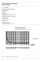
Page 46: ...t Pipe Installation Requirements Upstream 10 x D Downstream 5 x D D Flowmeter primary size Warm Up Phase 30 min Analog Output Effects Same as pulse output plus 0 1 of rate Standard Calibration Pulse Output Q 0 07 Qmax DN 0 5 of rate Q 0 07 Qmax DN 0 00035 Qmax DN Qmax DN max flowrate for the meter size at 10 m s Standard Calibration 0 5 of rate Fig 21 Metering System accuracy COPA XE MAG XE ...

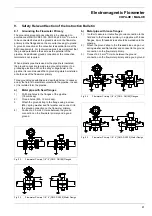
Page 47: ...In cases a and b the fluid is in electrical contact with the pipeline In case c it is isolated form the pipeline a Metal pipe with fixed flanges 1 Drill blind holes in the flanges of the pipeline 18 mm deep 2 Thread holes M6 12 mm deep 3 Attach the ground strap to the flange using a screw M6 spring washer and flat washer and connect it to the ground connection on the flomweter primary 4 Connect a ...

Page 48: ...hen there are stray currents in the pipeline it is recommended that a grounding plate be installed at both ends of the flowmeter primary 9 1 1 Grounding Models DE21_ and DE23_ The ground connections are made as shown in Fig 28 The fluid is grounded by its contact with the adapter so that an additional ground connection is not required Exception Flowmeter primaries with plastic solvent weld process...

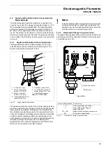
Page 49: ...or terminals strips A shielded excitation cable is located parallel to the signal leads in the cable assembly so that only one cable is required between the flowmeter primary and the converter To shield against magnetic pickup the cable incorporates an outer steel shield which is to be connected to the SE Terminals Note If plant conditions make it impossible to avoid proximity to electrical machin...

Page 50: ...the maximum submergence level Fig 33 Above this level the cable is installed using the cable connector included with the shipment in a water tight manner The hose is then attached to the hose connector using the threaded clamp ring Finally the connection box should be carefully secured Supply Power In Outputs SE Terminal Ground Signal Excitation Cable Fig 31 Converter Field Mount Housing View into...

Page 51: ...30 V On off ratio 1 4 Ton Toff fmax 5kHz 2 mA I 20 mA 16 V U 30 V 2 Contact Output function software selectable for System Monitoring Empty Pipe Max Min Alarm or F R Signal Terminals G2 P7 Optocoupler specifications 0 V UCEL 2 V 16 V UCEH 30 V 0 mA ICEH 0 2 mA 2 mA ICEL 220 mA 3 Contact Input function software selectable for External Zero Return or External Totalizer Reset Terminals G2 X1 Optocoup...

Page 52: ...Min Alarm or F R Signal Optocoupler specifications 0 V UCEL 2 V 16 V UCEH 30 V 0 mA ICEH 0 2 mA 2 mA ICEL 220 mA Terminals PA PA Connection for Profibus PA per IEC1158 2 see also Page 50 Terminals Current Output Terminals load 600 Ω 4 to 20 mA only Design b Same as Design a except Terminals A B Serial Data Link RS485 for Communication using ASCII Protocol Design c Same as Design a except Terminals...

Page 53: ...U 30 V 2 Contact Output Function software selectable for System Monitoring Empty Pipe Max Min Alarm or F R Signal Terminals G2 P7 Optocoupler specifications 0 V UCEL 2 V 16 V UCEH 30 V 0 mA ICEH 0 2 mA 2 mA ICEL 220 mA 3 Contact Input Function software selectable for External Zero Return or External Totalizer Reset Terminals G2 X1 Optocoupler 16 V U 30 V Ri 2kΩ 4 Current Output selectable Terminal...

Page 54: ...l Optocoupler specifications 0 V UCEL 2 V 16 V UCEH 30 V 0 mA ICEH 2 mA 0 2 mA ICEL 220 mA Terminals PA PA Connection for Profibus PA per IEC1158 2 see also Page 50 Terminals Current Output Terminals load 600 Ω 4 to 20 mA only Design b Same as Design a except Terminals A B Serial Data Link RS485 for Communication using ASCII Protocol Design c Same as Design a except Terminals VD A B GND Connection...

Page 55: ...al internal Pulse Output Active 24 V X1 24 V external internal Contact Input for External Zero Return G2 Contact setting Output is turned off when contact is closed RI 0 V Function software selectable RI 2 kΩ X1 24 V external internal External Totalizer Reset G2 Contact setting Internal totalizer value to zero when contact is closed RI 0 V or RI 2 kΩ P7 U RB external internal Contact Output for Sy...

Page 56: ... Max Min Alarm or F R Signal Function software selectable Pulse Output Optocoupler Ux V8 Profibus DP The resistors R1 R2 R3 are bus termination resistors They are to be installed when the instrument is connected at the end of the bus R1 390 Ω R2 220 Ω R3 390 Ω Profibus PA The resistor R and the capacitor C form the bus termination They are to be installed when the instrument is connected at the en...

Page 57: ...th max 1 m Incoming and outgoing cables on the same terminals Bus Terminations for Profibus DP Both ends of the bus must have bus terminations installed see Fig 41 In addition to the bus termination resistor R2 per the EIA RS 485 Standard a resistor R1 Pulldown to the data reference potential GND and a resistor R3 Pullup to the plus supply voltage VD are to be installed These two resistors assure ...

Page 58: ...ed shielded Cu cable per EN 50170 Type A is recommended Conductor area nominal 0 8 mm2 AWG 18 Loop resistance DC 44 Ω km Characteristic impedance at 31 25 kHz 100 Ω 20 Wave attenuation at 39 kHz 3 dB km Capacitive unsymmetry 2 nF km Max cable length 1900 m for use with standard Power Supply Type IV Segment Coupler in non Intrinsically Safe Design U 24 V Imax 500 mA Pmax 12 W Tap lead Max 30 60 m f...

Page 59: ...e buildings the supply power cables to the flowmeter are to installed with a switch or line switch which should be located in the vicinity of the flowmeter and identified accordingly The electrical connections between the flowmeter primary and the converter can only be made with the signal cable supplied by ABB Automation Products The connections are to be made in accordance with the appropriate I...

Page 60: ...n the flowmeter primary and the converter The instruments which belong together which are identified by the same end digits on the Instrument Tag e g A1 goes with B1 or A2 goes with B2 Check that the EEPROM is plugged into the socket on the display board of the converter see Section 10 5 A tag on this EEPROM contains the Order No with its end digits These end digits should be the same as those con...

Page 61: ... observe the Note Hazardous Material Information when returning the flowmeter primary to the ABB Automation Products factory for repair Notes for Opening the Housing The following notes must be observed when opening the housing of the converter All connection leads must be voltage free When the housing is open the EMC Protection is limited 10 7 Display Rotation Remove the housing cover screws The ...

Page 62: ...tionally be selected for the 1st or 2nd lines of the display Converter Housing Designs For Model COPA XE Compact Design with converter housing made of a light metal casting painted 60 µm thick coat center section dark grey RAL 7012 front and rear sections cover light gray RAL 9002 Option Stainless steel converter housing For Model MAG XE a Field mount housing made of light metal casting painted 60...

Page 63: ...gemax 0 001 1000 pulses unit 0 100 2000 ms 0 10 of flow range end value 0 125 99 99 seconds ON OFF 0 01 g cm3 5 0 g cm3 l s l min l h hl s hl min hl h m3 s m3 min m3 h igps igpm igph mdg gpm gph bbl s bbl min bbl h bls day bls min bls h kg s kg min kg h t s t min t h g s g min g h ml s ml min ml h Ml min Ml h Ml day lb s lb min lb h uton min uton h uton day kgal s kgal min kgal h l hl m3 igal gal ...

Page 64: ...ABB Automation Products GmbH Dransfelder Str 2 D 37079 Goettingen Tel 49 0 5 51 9 05 0 Fax 49 0 5 51 9 05 777 http www abb com automation ...

Reviews: