04-3275_OPM_ABB_CONCEPTPOWER_DPA_500kW_EN_REV-A.docx
Page 29/78 ABB
Modifications reserved
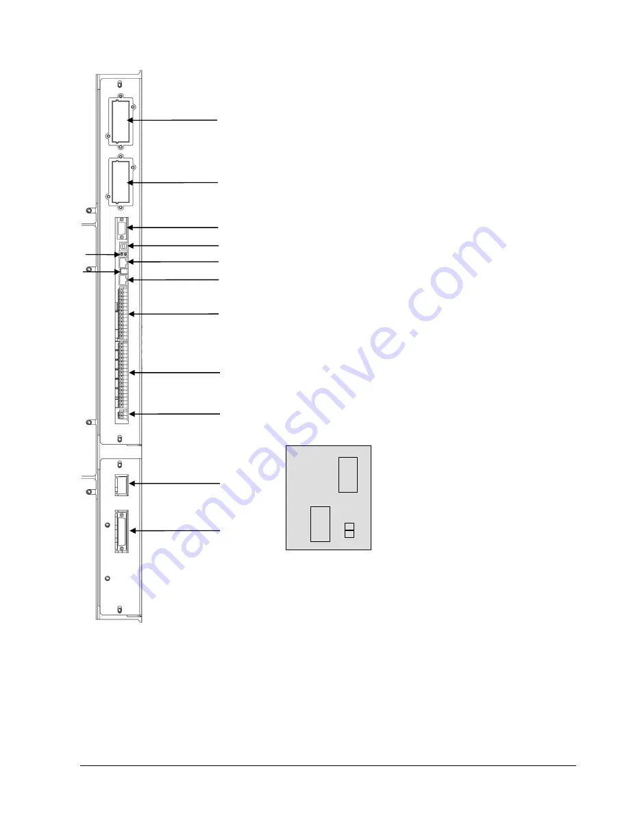
Figure 12: Customer interface board
1
2
3
8
6
4
9
10
11
12
13
5
1
Modem
Slot for optional Modem/Ethernet card ONLY
2
SNMP
Slot for optional SNMP card ONLY
3
JD1
RS232 Sub D9/female PC / laptop connection
4
USB
PC / laptop connection
5
2 LED’s
green/red LED showing the status of the interface board
6
JR3
Graphical display connection
7
SW2
DIP-SWITCH for Multidrop configuration
8
JR2
(RJ 45) Multidrop connection (multi-cabinet configuration)
9
X3
UPS inputs and 12VDC source (X3 5/6)
10
X2
UPS outputs dry ports (potential free contacts)
11
X1
Interlock Function
12
SW1-6
Multi-cabinet Configuration switch (see 5.1.6 and 6.1.2.4)
13
JD8
Parallel BUS connector
ONLY For paralleling cabinets use optional adapter:
JD5
Parallel BUS - Input Connector
JD6
Parallel BUS - Output Connector
7
Parallel
Adapter
JD 5
SW2-2
JD6


