4
…2
ELECTRICAL INSTALLATION
2.4
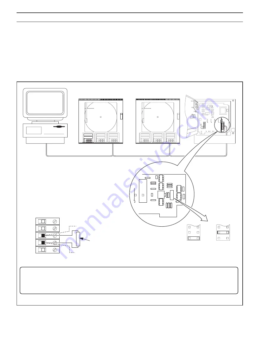
Termination Resistors – Fig. 2.3
For long transmission lines, termination resistors are required on the last slave in the chain and the host computer/computer
terminal – see Fig. 2.3. Under normal operating conditions the resistors are required at the receive inputs only. For 3-wire
operation the slave termination resistor is fitted to the serial module terminal board – see Fig. 2.3A. For 5-wire operation the slave
termination resistor is selected using plug-in links on the serial module – see Fig. 2.3B.
2.5
RS485/422 Standard
The RS485 standard quotes connection of thirty two slaves maximum, to any single driver (computer terminal or host computer);
the RS422 standard quotes connection of up to ten slaves. However, these numbers can be increased if the driver’s serial port
permits.
7
6
12 1
2
5
4
3
6
A – 3-wire Operation
120
Ω
External Termination Resistor – see
Note
Tx+/Rx+
Tx–/Rx–
B – 5-wire Operation
Termination
Resistor
Linked In –
see
Note
1
12
3
10
2
11
Termination
Resistor
Linked Out
3
10
2
11
1
12
PL2
PL2
PL2
Fig. 2.3 Slave Termination Resistors
Note
.
• For
3-wire
operation an external 120
Ω
resistor must be on the last slave in the chain. The resistor is fitted across
terminals 4 and 5 on the serial module terminal board.
• For
5-wire
operation the internal termination resistor on the last slave in the chain must be linked in.
Summary of Contents for C1900 Series
Page 24: ...22 NOTES ...
Page 25: ...23 NOTES ...
Page 26: ...24 NOTES ...
Page 27: ...Sales Software Service ...


