C1300
Advanced Circular Chart Recorder
2 Electrical Installation
6
IM/C1300–MOD
Rev. C
2.6 Serial Connections
All connections, apart from those for serial data communication, are made as shown in
Section 5
of the
User Guide (IM/C1300)
.
Make serial data connections as shown in Fig. 2.4. The type of cable used is dependent on the cable length:
Note.
Up to
10 slaves
can be connected to a single
RS422
adaptor card on a PC.
Up to
32 slaves
can be connected to a single
RS485
adaptor card on a PC.
The maximum serial data transmission line length for both
RS422
and
RS485
systems is 1200m (3,937 ft).
Up to 6m (20 ft)
– standard screened or twisted pair cable
Up to 300m (984 ft)
– twin twisted pair with overall foil screen and an integral drain wire, e.g. Belden 9502 or equivalent
Up to 1200m (3,937 ft)
– twin twisted pair with separate foil screens and integral drain wires for each pair,
e.g. Belden 9729 or equivalent
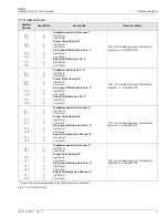
Fig. 2.4 Serial Module Connections
C1300 Serial Module Terminal Board
OPTO22 Board Pin Identification
Terminal Number
Connections
Part Number AC24 AT & AC34
Connections
4
TX+
4
8
TX+
RX+
5
TX–
5
9
TX–
RX–
8
GND
3
GND
Table 2.1 Terminal and Pin Identification for 2-wire Operation
C1300 Serial Module Terminal Board
OPTO22 Board Pin Identification
Terminal Number
Connections
Part Number AC24 AT & AC34
Connections
4
TX+
8
RX+
5
TX–
9
RX–
6
RX–
5
TX–
7
RX+
4
TX+
8
GND
3
GND
Table 2.2 Terminal and Pin Identification for 4-wire Operation
OPTO22 Adaptor
Board Connections
4
7
6
Serial Module
Connections
5
8
Tx+
Tx
GND
Tx+
Tx
Rx+
Rx
GND
8
5
4
9
3
Screen
A Connections for 2-wire Operation
4
7
6
Serial Module
Connections
5
8
Tx+
Tx
Rx+
Rx
GND
Tx+
Tx
Rx+
Rx
GND
OPTO22 Adaptor
Board Connections
8
5
4
9
3
Screen
B Connections for 4-wire Operation


