C1300
Advanced Circular Chart Recorder
5 Modbus Functions
10
IM/C1300–MOD
Rev. C
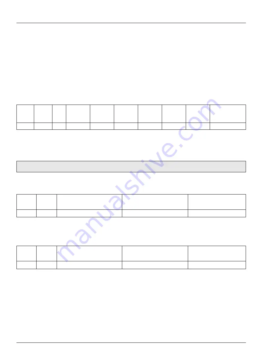
5.2.2 Read Holding Register Response
The addressed slave responds with its address and function code, followed by the information field. The information field contains 1
byte describing the quantity of data bytes to be returned. The contents of each register requested (DATA) is two bytes, the first byte
includes the high order bits and the second the low order bits.
Example
– the response to the read holding register query shows the following:
Alarm trip A1
–
150
Alarm trip B1
–
50
Alarm trip C1
–
100
Alarm trip D1
–
400
Alarm trip A2
–
0
Alarm trip B2
–
0
5.3 Force Single Coil – Function Code 05
5.3.1 Force Single Coil Query
This message forces a single coil either ON or OFF. The data value 65,280 (FF00 HEX) sets the coil ON and the value zero turns it
OFF. All other values are illegal and do not affect the coil.
The use of slave address zero (broadcast mode) forces all attached slaves to modify the desired coil.
Example
– a force single coil request to switch ON coil address 149 (auto/manual state, channel 1) in slave 01 is shown below.
5.3.2 Force Single Coil Response
The response is confirmation of the query after the coil state has been altered.
Example:
Address
Function
Byte
Count
Holding
Register 121
Holding
Register 122
Holding
Register 123
Holding
Register 124
Holding
Register 125
Holding
Register 126
Error Check Field
(CRC-16)
High
Low
High
Low
High
Low
High
Low
High
Low
High
Low
01
03
0C
00
96
00
32
00
64
00
90
00
00
00
00
D9
91
Note.
To write to a coil the coil offset address must be used, e.g. to write to coil 149, the coil address 148(94H) is transmitted.
Address
Function
Coil Offset
Data Value High
Error Check Field
(CRC-16)
High
Low
High
Low
01
05
00
94
FF
00
CD
D6
Address
Function
Coil Offset
Data Value High
Error Check Field
(CRC-16)
High
Low
High
Low
01
05
00
94
FF
00
CD
D6


