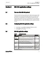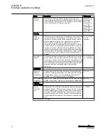
Name
Description
Value range
Stop bits
Number of stop bits used on IEC-101 serial communication
1, 2
Use HW flow
control
HW flow control mechanism (RTS/CTS) on IEC-101 serial
communication. Note: The HW handshaking is available only on
RS-232 mode.
No, Yes
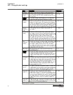
Network
settings
The Network settings define the general TCP/IP networking
properties between the device and the IEC-104 master.
Network
protocol
Network protocol defines the network transmission layer protocol
(either TCP or UDP) used on IEC-104 network communication.
The IEC-104 standard protocol uses TCP, but for reliable slow
speed packet switched networks (for example Mobitex), the UDP
protocol can be used to minimize the packets transmitted over
network. Note: The IEC-104 standard specifies only TCP protocol.
UDP, TCP
Network
protocol to
listen
TCP or UDP port number to listen for incoming IEC-104
connections
0...65000
Network idle
timeout
Network idle timeout defines the idle timeout of the network
connection in seconds. If there is no network data received during
the specified interval, the connection is closed by the device. This
parameter is required in order to detect partially closed
connections and release the resources for new connections
especially if the
New connection priority parameter is disabled.
Value “0” disables the network idle timeout detection. The network
idle timeout must be longer than IEC-104 link test interval (t3).
0...65000
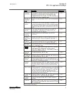
New
connection
priority
It defines the action when a new connection request arrives while
a connection is already active. If the set value is ”No”, the new
connection is rejected. If the set value is ”Yes”, the present
connection is terminated and the new connection is accepted. It is
recommendable to set this value to “Yes” in normal configurations
having only one IEC-104 master.
No, Yes
Max clients
Max clients defines the maximun number of connections
(redundancy group).
1...3
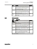
IEC-104
settings
The IEC-104 settings define the properties of IEC-104 link layer
and application layer parameters as described in the IEC
60870-5-104 standard. The IEC-104 communication is carried out
between the device and the IEC-104 master over the TCP/IP
network.
TX window
size (k)
TX window size defines the maximum number of I format APDU
packets the device may send before requiring the IEC-104 master
to acknowledge them. If there are
k unacknowledged frames sent
the device stops polling IEC-101 slave for events until
acknowledgement is received. The
k must be always less than the
maximum sequence number defined below. The IEC-104
standard suggests
k to be 12.
1...20
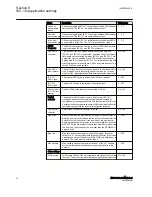
RX window
size (w)
RX window size defines the maximum number of I format APDU
packets the device may receive before sending acknowledgement
to the IEC-104 master. The
w should not exceed two-thirds of TX
window size
k. The IEC-104 standard suggests w to be 8.
1...20
I frames TX
timeout (t1)
It defines the timeout in seconds the device waits for
acknowledgement from IEC-104 master after sending last I format
APDU or control frame (e.g. link test). If no acknowledgement is
received during the defined time the device will close the network
connection and the IEC-101 link. The t1 must be longer than the
network round-trip-time. The IEC-104 standard suggests 15
seconds.
1...255
I frames RX
timeout (t2)
This defines the timeout in seconds from the last received I format
APDU before sending acknowledgement. The t2 must be smaller
than t1. The IEC-104 standard suggests 10.
1...255
Table continues on next page
Section 8
1MRS758460 B
IEC-104 application settings
30
ARG600 Dual SIM Variant
User Manual


