background image

Table 3:

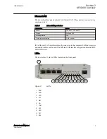
Description of available LEDs

LED

Label

State

Description

1

ERR

On

Unit is restarting. LED should be turned

off after restart (usually about 30

seconds)

Flashing

Error with power supply. Device

restarts constantly.

Off

Device is operating normally

2

RUN

Flashing

Device is operating normally

Off

If the unit is turned on and RUN LED is

not blinking, the system has an error

and is waiting for restart. The unit

should restart soon.

3

VPN

On

VPN connection is up

Flashing

VPN connection is starting

Off

VPN connection is disabled

4

FW

-

Reserved for future use

5

SIM

On

SIM card has been initialized and it is

ready for use

Flashing

SIM card initialization is in progress

Off

SIM card is not used

6

SIG

On

Signal level is normal or good

Flashing

Signal level is weak

Off

There is no signal

7

COM

On

Cellular network (Wireless WAN)

connection is up

Flashing

Cellular connection is starting. If the

connection is not coming up, check the

SIM and SIG LEDs

Off

Cellular connection is stopped

8

APP

-

Reserved for future use

9

USR

-

Reserved for future use

10

RS1

-

Reserved for future use

11

RS2

-

Reserved for future use

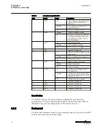
Reset button

It is possible to restore the factory settings by pushing the reset button for
approximately 15 seconds and releasing the button, when all the status LEDs are
illuminated. Any previous configuration will be lost after the reset.

2.2.2 

Back panel

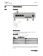
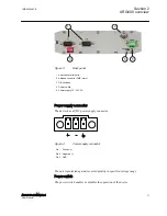
The device has an antenna connector, a power supply connector, a power switch, DIP
switches and serial ports on the back panel.

Section 2

1MRS758460 B

ARG600 overview

10

ARG600 Dual SIM Variant

User Manual

Summary of Contents for ARG600 ANSI

Page 1: ...Wireless Gateway ARG600 Dual SIM Variant User Manual ...
Page 2: ......

Page 3: ...Document ID 1MRS758460 Issued 2017 09 22 Revision B Product version 3 4 Copyright 2017 ABB All rights reserved ...

Page 4: ...d to a third party nor used for any unauthorized purpose The software or hardware described in this document is furnished under a license and may be used copied or disclosed only in accordance with the terms of such license Trademarks Warranty Please inquire about the terms of warranty from your nearest ABB representative www abb com substationautomation ...

Page 5: ...cted and communicate data and information via a network interface which should be connected to a secure network It is the sole responsibility of the person or entity responsible for network administration to ensure a secure connection to the network and to take the necessary measures such as but not limited to installation of firewalls application of authentication measures encryption of data inst...

Page 6: ...n systems air traffic control direct life support machines or weapons systems in which the failure of the hardware or software described in this manual could lead directly to death personal injury or severe physical or environmental damage To prevent damage both the product and any terminal devices must always be switched off before connecting or disconnecting any cables It should be ascertained t...

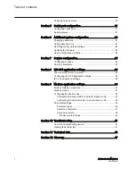
Page 7: ... 3 Getting started 13 Connecting cables 13 Connection principle 13 Logging in 13 User interface 14 Ethernet port roles 14 Setting Ethernet port function to LAN 15 Configuring mobile WAN 15 Configuring the default route 15 Section 4 Network configuration 17 Defining host and domain names 17 Configuring communication interfaces 17 Configuring Ethernet LAN 17 Configuring Ethernet WAN 17 Configuring t...

Page 8: ...of the IEC 104 protocol 29 Configuring IEC 104 application settings 29 IEC 104 application settings 29 Section 9 Modbus application settings 33 Modbus Gateway properties 33 Modbus modes 33 Configuring Modbus modes 35 Configuring the serial master to network slaves mode 35 Configuring the network master to serial slaves mode 36 Parameter settings 36 Parameter types 36 Common parameters 37 Route par...

Page 9: ...ng principles of Internet technology 1 3 Product documentation 1 3 1 Product documentation set Product series and product specific manuals can be downloaded from the ABB Web site http www abb com substationautomation 1 3 2 Document revision history Document revision date Product version History A 2015 12 18 A First release B 2017 09 22 3 4 Content updated to correspond to the product version Downl...

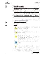
Page 10: ...nventions 1 4 1 Symbols The electrical warning icon indicates the presence of a hazard which could result in electrical shock The warning icon indicates the presence of a hazard which could result in personal injury The caution icon indicates important information or warning related to the concept discussed in the text It might indicate the presence of a hazard which could result in corruption of ...

Page 11: ...nyms are spelled out in the glossary The glossary also contains definitions of important terms Menu paths are presented in bold Select Main menu Settings Parameter names are shown in italics The function can be enabled and disabled with the Operation setting Parameter values are indicated with quotation marks The corresponding parameter values are On and Off 1MRS758460 B Section 1 Introduction ARG...

Page 12: ...6 ...

Page 13: ...a DNP3 TCP SCADA system In this case the DNP3 protocol is transferred over TCP IP communication transparent serial gateway mode Wireless Gateway ARG600 can be utilized for various industrial and utility applications to maximize the benefits Industrial grade TCP IP router several serial and TCP IP based field devices can be integrated into a central supervisory and control system SCADA Integrated p...

Page 14: ...hernet cable is 100 m Ethernet WAN The device has one physical port for Ethernet WAN Table 1 Ethernet WAN specifications Description Value Number of ports 1 Speed 10Base T 100Base TX Duplex Half and Full Autonegotiation Yes Recommended cabling Cat5 or better If the Ethernet WAN interface is directly connected to the computer a crossover cable must be used The Ethernet WAN interface does not suppor...

Page 15: ...the Ethernet LAN interface is directly connected to the computer both the crossover and straight cables can be used The Ethernet LAN interface supports automatic MDI MDIX detection LEDs The device has 11 status LEDs located on the front panel 1 2 3 4 5 6 7 8 9 10 11 GUID 2F75FFBF 5082 49D1 951E CDA1A690E70C V1 EN Figure 2 LEDs 1 ERR 2 RUN 3 VPN 4 FW 5 SIM 6 SIG 7 COM 8 APP 9 USR 10 RS1 11 RS2 1MRS...

Page 16: ...rd is not used 6 SIG On Signal level is normal or good Flashing Signal level is weak Off There is no signal 7 COM On Cellular network Wireless WAN connection is up Flashing Cellular connection is starting If the connection is not coming up check the SIM and SIG LEDs Off Cellular connection is stopped 8 APP Reserved for future use 9 USR Reserved for future use 10 RS1 Reserved for future use 11 RS2 ...

Page 17: ...connector The device has a VDC power supply connector GUID E514AE4B D431 49E6 ACA4 930E36C42977 V1 EN Figure 4 Power supply connector Pin 1 Positive Pin 2 Negative Pin 3 GND The unit is protected against reversed polarity in specified voltage range Power switch The power switch enables or disables the operation of the device 1MRS758460 B Section 2 ARG600 overview ARG600 Dual SIM Variant 11 User Ma...

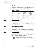
Page 18: ... 0 OFF 1 ON RS 485 termination 2 3 DIN rail mounting The device has mounting holes for optional DIN rail mounting brackets The order code for the DIN rail mounting kit is 2RCA028233 DIN rail clips set consisting of a plastic clip and screws 2 4 Product information label The product label contains basic information about the unit such as product name serial number and Ethernet MAC address 2 5 Firmw...

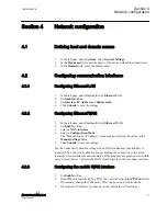
Page 19: ...G cellular network connection The Mobile WAN interface is used for connecting the device to the cellular network The Ethernet LAN is used for connecting other Ethernet devices to the device s local network The WAN interfaces can be configured to create a redundant system where one WAN automatically receives traffic if the other one goes down For example if the primary Ethernet connection goes down...

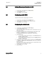
Page 20: ... Page opens 3 2 1 User interface The user interface consists of views that can be opened from the menu in the left pane 3 3 Ethernet port roles The device has three switched LAN ports and one WAN port The LAN interface s IP address is by default 10 10 10 10 255 0 0 0 The LAN IP address is a user configurable static address without a DHCP option The WAN interface is configured by default as a DHCP ...

Page 21: ...figuring Ethernet WAN as the default gateway in the left pane under Network click Ethernet Port and set Port function to WAN If configuring Mobile WAN as the default gateway skip this step 4 Set the default route To select Ethernet WAN as the default gateway under Primary WAN set Interface to Ethernet WAN To select Mobile WAN as the default gateway under Primary WAN set Interface to Mobile WAN 5 I...

Page 22: ...16 ...

Page 23: ...on Mode The Manual Static IP Address mode requires entering the values in the Manual Settings fields 5 Click Submit to save the settings Use the Connectivity Monitor settings when WAN redundancy functionality is required The Connectivity Monitor keeps checking the connection to the given remote host to determine the network status If the ping does not get an answer within a given time window it in...

Page 24: ...If the device acts as a wireless router to Ethernet devices and DNS is needed enter the DNS settings Set DNS Selection to From Network to set up the device to receive DNS server IP addresses automatically from the cellular network Set DNS Selection to Manual to set up the device to use DNS servers manually defined in the DNS Servers field 6 Click Submit to save the settings 7 Restart the device to...

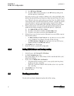
Page 25: ...figured to enable default route Backup WAN Interface None Mobile WAN Ethernet WAN Secondary Backup WAN Interface None Mobile WAN Ethernet WAN Ethernet WAN Secondary OpenVPN Client Settings Interface Any WAN Ethernet WAN Wireless WAN Ethernet LAN This setting defines which interface to use for connection Routing mode None Host Net Default route This setting defines how the routing is configured wit...

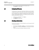
Page 26: ... DHCP and the device forwards the name queries to the actual DNS server and back to the LAN devices 1 In the left pane under Services click Common 2 Set Use DNS Proxy to Yes 3 Click Submit to save the settings 4 6 Checking network status The device has user interface views and LEDs that show network status and are useful in troubleshooting situations 1 In the left pane under System click Status to...

Page 27: ...ASCII serial device protocol 5 2 Serial gateway The serial gateway feature enables data from the serial port attached device to be routed to Ethernet mobile network serial over IP and vice versa Serial gateway processes the transmitted data transparently and does not alter it any way except for buffering it for transmission Because of the transparent communication any protocols can be used in actu...

Page 28: ...22 ...

Page 29: ...ime The time zone can be set so that the device shows the time in a local format There is also an NTP server in the device NTP client and server this enables the device to work as NTP server for the LAN devices 3 Click Submit under the Mode setting The lower part of the view is updated if the setting changed 4 Check the time and date settings In the Automatic NTP mode check the settings under Curr...

Page 30: ...3 Select the new firmware file 4 Click Update A confirmation dialog opens 5 Click OK to confirm firmware The update takes a few minutes 6 Once the update is finished restart the device 6 5 Saving configuration profiles It is possible to save the device s configuration in a profile for use in other devices or as a backup when updating the firmware The configuration can be exported as an XML file 1 ...

Page 31: ...uses it s hostname eg arctic 02xxyy No Yes mDNS responder The multicast domain name system is a protocol that enables Mac OS X machines on LAN to find the device using its hostname for example arctic 02xxyy No Yes SSH Server The SSH secure shell is an encrypted network protocol for safe remote command line connections It is replacing the Telnet protocol SSH Server Determines if logging into the de...

Page 32: ...t IP address Usually the last IP address of the subnet Default lease time Given to clients that don t request a specific lease length empty 10800 Maximum lease time The maximum lease time given to clients empty 10800 NTP Servers List of NTP servers comma separated LPR Servers List of line printer LPR servers comma separated WINS Servers List of WINS servers comma separated Table 8 DynDNS client Na...

Page 33: ...s 161 Table 10 Arctic Patrol Name Description Value range Basic Information Enabled Enables Viola Patrol No Yes Server IP Port Server IP address and the port server listens If no value is given the value is 10000 Connection interval Defines how often to report to server Backup active configuration to server When set to Yes copies encrypted version of XML configuration file to server No Yes Registr...

Page 34: ...28 ...

Page 35: ...and change settings in the view that opens 3 Click Submit to save the settings 8 3 IEC 104 application settings Table 11 IEC 104 application settings Name Description Value range Basic settings Enable IEC 104 gateway Enables or disables IEC 104 to IEC 101 gateway functionality No Yes Serial settings The serial settings define the properties of physical serial communication between the device and a...

Page 36: ...is accepted It is recommendable to set this value to Yes in normal configurations having only one IEC 104 master No Yes Max clients Max clients defines the maximun number of connections redundancy group 1 3 IEC 104 settings The IEC 104 settings define the properties of IEC 104 link layer and application layer parameters as described in the IEC 60870 5 104 standard The IEC 104 communication is carr...

Page 37: ...and application layer parameters as described in the IEC 60870 5 101 standard The IEC 101 communication is carried out between the device and a IEC 101 Slave link address The link level address of IEC 101 slave 1 65000 Link address field length Defines the length of the IEC 101 link level address field in bytes The link level address of IEC 101 slave 1 2 Event poll interval Event poll interval def...

Page 38: ...iginal type 0 255 Convert short IEC 101 time stamps Defines if 56 bit timestamps are converted to 24 bit No Yes Packet collector The packet collector can be used to collect many IEC 101 messages and events to a single network packet instead of sending every message separately This function is useful for slow packet switched communication network for example Mobitex for speeding up especially the g...

Page 39: ...nd Modbus ASCII over UDP network protocols Generates and filters out gateway exceptions Routes traffic on the network based on Modbus addressing enabling intelligent use of network resources Makes automatic connection management Enables multiple server sessions over network Offers unlimited amount of Masters on serial or Network side Offers 30 routes over network to slaves 9 2 Modbus modes Serial ...

Page 40: ...essing allows intelligent use of network resources which is especially useful for pay per use networks like GPRS The settings consist of two parts common settings and settings for each route Network master to serial slaves When the PLC RTU slaves supporting serial based Modbus communication are required to be controlled over TCP IP networks the device on the slave side must be in the Network maste...

Page 41: ... if the reply is corrupted the device sends gateway exception message back to the master if the exception generation is enabled Otherwise the reply is returned Multiple masters can connect simultaneously to the Gateway which handles the multiplexing between masters 9 3 Configuring Modbus modes 9 3 1 Configuring the serial master to network slaves mode 1 In the left pane under Serial Port and I O c...

Page 42: ...way to Yes 3 Set Gateway mode to Network master to serial slaves 4 Set the parameters under Serial settings Protocols Framing Exceptions and Network server settings as the network and the Modbus master and slaves require See Chapter Common parameters for additional information and recommendations 5 Click Submit to save the settings 6 Restart the device 9 4 Parameter settings 9 4 1 Parameter types ...

Page 43: ...d number depends on how many data bits the connected Modbus equipment supports Generally Modbus RTU communication uses 8 data bits and Modbus ASCII communication uses 7 data bits 5 6 7 8 Auto Parity Defines the parity method used in Modbus serial communication If set to None no parity method is used If set to Even an even parity bit is generated and inspected If set to Odd odd parity bits are gene...

Page 44: ...millionths of a second that marks the end of Modbus frame in serial communication If the value is zero the device uses the standard 4 character time The recommendation is to use a value as small as possible to speed up communication and increase the value if problems arise Some PC programs can insert unexpected delays between serial characters 0 2 000 000 0 2 seconds Exceptions Generate gateway ex...

Page 45: ...me Description Value range Route information Route in use Each IP address and TCP UDP port of slaves needs to be defined on separate route entries No Yes Host name or IP address The IP address or host name of a device where packets are routed by that entry If host names are used the DNS server IP address is required to be defined in the network settings The Network Protocol setting on Common param...

Page 46: ...able TCP keepalive If set to Yes connection testing with TCP keepalive packets between the master and slave devices is enabled for TCP network communication The recommended setting is Yes if the polling interval or idle timeout is very long No Yes 9 4 3 1 Modbus route settings The route entries define how Modbus packets are routed on network from the serial master to network slaves Up to 30 routes...

Page 47: ...being used Access to web user interface does not work Web user interface uses HTTPS for secure web access and it must be specified on the web browser address field like in this example https 10 10 10 10 Access to the Internet with a laptop connected to the device does not work Test the wireless connection 1 Configure wireless connection and verify if it is connected to the network 2 Connect a lapt...

Page 48: ...42 ...

Page 49: ...E Environmental conditions Temperature range 30 70 C operating 40 85 C storage Humidity 5 85 RH non condensing Protection class IP30 Table 17 Supported protocols Master protocol Slave protocol IEC 60870 5 104 IEC 60870 5 101 Modbus TCP Modbus RTU ASCII TCP IP UDP IP DNP3 Serial gateway serial port data stream such as DNP3 Table 18 Network interfaces Description Value Ethernet ports Ethernet LAN 10...

Page 50: ... 800 bps Data bits 7 or 8 Stop bits 1 or 2 Parity None Even Odd Flow control None RTS CTS Protection 15 kV ESD and short circuit Table 19 Wireless network interfaces WAN Product Air interface Frequency Maximum data rate ARG600A2625NA GPRS EDGE 1900 1800 900 850 MHz 85 2 Kbps 236 8 kbps WCDMA HSPA 2100 1900 900 850 MHz 21 Mbit s LTE 2600 band 7 2100 band 1 1800 band 3 900 band 8 800 band 20 MHz 100...

Page 51: ...tests according to the test specification ETSI EN 301489 1 V1 8 1 2008 04 Electrostatic discharge ESD EN 61000 4 2 2008 12 Radiated radiofrequency electromagnetic field EN 61000 4 3 2006 02 Table 22 EMC compliancy Description Reference Standard ETSI EN 301489 1 V1 8 1 2008 04 Table 23 RoHS and REACH compliancy Description Reference Directive RoHS directive 2002 95 EC REACH directive 2006 1907 EC 1...

Page 52: ...46 ...

Page 53: ...nologies into a LAN FME For Mobile Equipment FW Forward LAN Local area network LED Light emitting diode NTP Network time protocol PAP Password authentication protocol RAM Random access memory RISC Reduced Instruction Set Computer RJ 45 Galvanic connector type RS 422 Serial communication standard EIA 422 RS 485 Serial link according to EIA standard RS485 RTS Ready to send SCADA Supervision control ...

Page 54: ...48 ...

Page 55: ...49 ...

Page 56: ... Voltage Products Distribution Automation P O Box 699 FI 65101 VAASA Finland Phone 358 10 22 11 Fax 358 10 22 41094 www abb com mediumvoltage www abb com substationautomation 1MRS758460 B Copyright 2017 ABB All rights reserved ...

Reviews: