


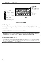
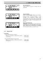


26
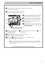
Lower Display
Time
Flow Velocity
Pressure
Left Battery Warning
Sensor Fault
Empty Pipe condition
Mains Failure
Right Battery Warning
Upper Display
Date
Forward Flow Total
Reverse Flow Total
Net Flow Total
Pictorial Displays
Warning annunciators
8
gal
m
3
AB
CD
.8.8.8.80
f t m
3
/ h M G D
g a l / s m B a r p s i
0
-
88888.888.
…4
START-UP AND OPERATION
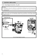
4.3
Display Activation
For normal operation, activate the light sensitive display by first covering the display area totally.
On removing the covering, the display activates and cycles through the programmed set of display
measurements.
With external AC power applied, the display is permanently active.
Information.
For the use of local or remote serial communication and how to alter the displayed set
of measurements, or instrument setup, see the Quick Reference Programming Guide.
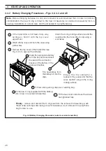
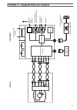
4.4
Replacing a Battery – Fig. 4.3
Note.
Each battery must be connected to the cable from the same side of the termination area as the
battery position in the battery holder or lid. For dual battery units, replace only the battery indicated by
the battery legend described on the following page.
Fig. 4.2 Location of Controls


