____________________________________________________________________________________________________________
V2
AC500 Hardware
1-47 System
data
AC500 / Issued: 05.2007
Diagnosis
The diagnosis telegram provides detailed information if there is any problem, particularly in the process.
A trip caused by overload of a motor is an example. Diagnosis data are automatically read by the
PROFIBUS DP master if it gets a general fault info within a monitoring telegram.
Complete diagnosis telegram:
PROFIBUS DP
PROFIBUS DP with PDP21, PDP22
6 bytes
Standard diagnosis data
6 bytes
Standard diagnosis data
1 byte +
1 byte
PDP21, PDP22 length of slave
diagnosis
x bytes
User-specific diagnosis
data
n bytes
Device-specific
Remark: Diagnosis function blocks provide additional 3 bytes diagnosis data that are created by the bus
master.
Configuration, Identification and other data
Configuration, identification and other data are necessary to start the operation and communication with
the PROFIBUS DP slave. These data is created during configuring/selecting the bus line including the
slaves/devices and is sent to the FieldBusPlugs directly after power-up.
All slaves compare the expected configuration with their real configuration and confirm if they agree as a
supposition to start the data exchange.
Additionally some general data such as baud rate and time-out are transferred.
Parameters
Parameters are necessary to adapt the device to the process.
E.g., for the device UMC22 the parameter "Set current" that has to be set correctly to enable the UMC22
to protect the connected motor perfectly against overload.
Parameters can also include service-oriented data such as "Operation hours".
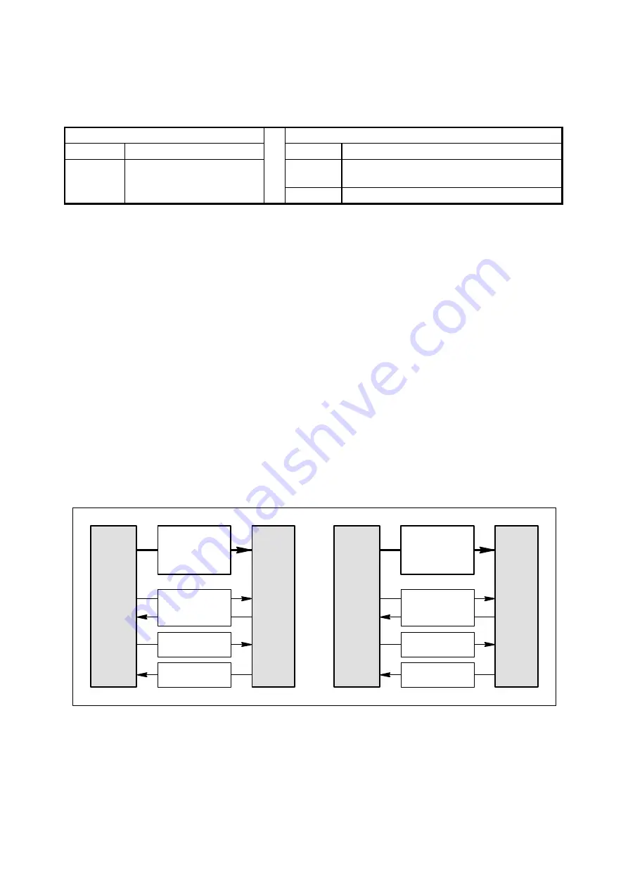
The main difference between the PROFIBUS DP versions DP-V0 and DP-V1 is:
DP/V0
Master
Parameters
only as block
DP/V0
Slave
Commands
Monitorings
Configuration
Diagnosis
DP/V1
Master
Parameters
as single
or as block
DP/V1
Slave
Commands
Monitorings
Configuration
Diagnosis
Figure: Parameters DP-V0 and DP-V1
DP-V0 only allows to write the complete parameter set in one block.
The bus master sends the parameter block to the slave during power-up of the slave/device. Some
control systems also allow to send the parameter block during normal operation.


