background image

ABB 

IB 6.2.15.7-1C 

M

ECHANISM


AND

 O

PERATION


(Refer to Fig. 2A And 2B) 

The ADVAC™ medium voltage circuit breaker uses a spring for stored energy.  The Closing Spring (11) is a toroidal 
spring.  This spring supplies the energy necessary to close the breaker and assists with the opening.  During the 
closing operation, Opening Springs (6) (compression type) are charged along with Contact Springs (4) (also 
compression type) in the pole assembly.  During the opening operation, the Contact Springs and Opening Springs 
supply the driving force to open the interrupter contacts. 

D

ESCRIPTION

 of 

M

ECHANISM

 O

PERATION

(Refer to Fig. 2A And 2B) 

1. Manual or electrical charging rotates the Closing Spring (11) 360

°

 to charge 

a. Motor Limit Switch (17) changes state and removes control power from the motor 
b. Closing Spring Charged/Discharged Indicator (28) changes to show CHARGED 
c. Close Trigger (20) is set against Half Shaft (19b) 

2. Manual or electric close rotates Half Shaft to release Close Trigger 

a. Close Trigger releases Stop Disk (9) through a series of linkages 
b. The Closing Spring (11) rotates Main Shaft (12) 270

°


c. The Cams (8) fixed on Main Shaft actuate Rocker Arms (7) for each pole 

 Rocker Arms compress Opening Springs (6) 

 Rocker Arms drive interrupter Push Rods (5) 

 Push Rods close Moving Contact in the Vacuum Interrupter (3) 

 Push Rods charge Contact Springs (4) 

d. Main Shaft actuates Auxiliary Shaft (15) changing Auxiliary Contacts (16) 

 52a contacts close 

 52b contacts open 

3. Manual or electric opening rotates other half shaft (19a) to release Open Trigger (21) 

a. Open Trigger releases Stop Disk through a series of linkages 
b. Opening Springs, Contact Springs and Closing Spring discharge, rotating the Main Shaft 90

°

 (discharging the 

360

°

 charge on the Closing Spring) 

c. Contact Springs discharge driving Push Rod to begin opening the Vacuum Interrupter Contacts 
d. Opening Springs discharge driving the Rocker Arms to fully open the Vacuum Interrupter Contacts 
e. Closing Spring discharges, rotating the Cams 90

°


f.  Main Shaft actuates Auxiliary Shaft changing Auxiliary Contacts 

               •

 52a contacts open ; 52b contacts close


MECHANISM AND OPERATION


Summary of Contents for ADVAC 03

Page 1: ...1 ABB IB 6 2 15 7 1C ADVACTM Model 03 Medium Voltage Vacuum Power Circuit Breakers and Auxiliary Installation Maintenance Instructions IB 6 2 15 7 1C November 2005 ...

Page 2: ...ion of Mechanism Operation 9 Interlocks 11 Manual Operation 12 Electrical Operation 13 Control Scheme 14 MAINTENANCE 16 Mechanism 16 Truck 18 Control Wiring 19 Primary Circuit 19 G T DEVICE 21 DUMMY BREAKER DEVICE 23 OPTIONAL ACCESSORIES 24 Lifting Hook 24 APPENDICES 25 Appendix A Basic Breaker Layout 25 Appendix B Basic Breaker Dimensions and Weights 26 Appendix C Close Open Coil Data 29 Appendix...

Page 3: ...r unit Intended for use in SafeGearTM Advance or abbreviated versions of these switchgear designs Contains all racking interlocks and racking features required by ANSI standards Automatic primary and secondary disconnects Provides three operating positions disconnect test and connect Meets all applicable ANSI standards C37 09 C37 04 C37 06 FIXED MOUNT Intended to be mounted as a stationary device ...

Page 4: ...ed with installation operation and maintenance of these breakers the following recommendations must be followed Only qualified persons as defined in the National Electric Safety Code who are familiar with the installation and maintenance of medium voltage circuits and equipment should be permitted to work on these breakers Read these instructions carefully before attempting any installation operat...

Page 5: ...mptly notify the nearest District Office Information specifying the purchase order number carton number and part numbers of damaged or missing parts should accompany the claim HANDLING ADVAC circuit breaker shipping containers are designed to be handled by a fork lift Once removed from the shipping container the circuit breaker wheels are designed to move the breaker across a smooth paved surface ...

Page 6: ...partment 2 Pull handles 10 to center this withdraws Cell Interlock Tabs 11 allowing breaker to be inserted 3 Push breaker into breaker compartment with handles Interlocks may restrict insertion Ref Interlocks 4 Align Cell Interlock Tabs with Circuit Breaker Compartment Slots A 5 Push Handles out to fully engage Cell Interlock Tabs into Circuit Breaker Compartment Slots 6 Visually check that Cell I...

Page 7: ...en Test and Connect positions 3 Once the Breaker is Fully in the connect position and the positive lock position has been established It is recom mended that the racking screw be turned in the counterclockwise direction to release the pressure on the locking mechanism to insure positive engagement of the mechanical electrical interlocks DISCONNECT THROUGH TEST 1 Perform visual inspection of the Ci...

Page 8: ...HEEL RAILS F SHUTTERS D E F A C B Figure 1 Basic Cell Notes A Closed door racking is recommended between ALL positions DISCONNECT TEST CONNECT Approximate Distance from Disconnect 0 MM 0 REVOLUTIONS 0 INCHES 40 MM 4 REVOLUTIONS 1 57 INCHES 250 MM 25 REVOLUTIONS 9 84 INCHES Manual Operation YES YES NOT RECOMMENDED Electrical Operation NO YES YES Control Power Available NO YES YES Shutter CLOSED CLO...

Page 9: ...ase Close Trigger a Close Trigger releases Stop Disk 9 through a series of linkages b The Closing Spring 11 rotates Main Shaft 12 270 c The Cams 8 fixed on Main Shaft actuate Rocker Arms 7 for each pole Rocker Arms compress Opening Springs 6 Rocker Arms drive interrupter Push Rods 5 Push Rods close Moving Contact in the Vacuum Interrupter 3 Push Rods charge Contact Springs 4 d Main Shaft actuates ...

Page 10: ...y 15 Auxilliary Shaft 16 Auxilliary Contacts 17 Motor Limit Switch 18 Close Push Button 19a Close Half Shaft 19b Open Half Shaft 20 Closing Trigger 21 Opening Trigger 22 Roller contacts 23 Operating Mechanism Housing 24 Epoxy resin Pole enclosure 25 Open Push Button 26 Charging Motor 27 Tripping Coil 28 Spring Charged indicator 29 Breaker Status Indicator FIGURE 2 MECH AND CONTROLS MECHANISM AND A...

Page 11: ...he breaker in any direction from any positive position Disconnect Test or Connect The release lever is blocked from actuation when the breaker is CLOSED The ability to close the breaker is blocked unless the breaker is in one of the three positive positions INTERFERENCE BLOCKING A code plate in the breaker compartment prevents underrated breakers from being inserted into higher rated compartments ...

Page 12: ...ker via Close Push Button 18 a Breaker Closes Close Open Indicator changes to CLOSED Closing Spring Charged Discharged Indicator changes to DISCHARGED b Breaker ready to perform Open O operation if O C O is desired see Step 7 6 Manual open breaker via Open Push Button 25 a Breaker opens Close Open Indicator changes to OPEN Closing Spring Charged Discharged Indicator remains DISCHARGED b No additio...

Page 13: ...form C O operation 3 Close breaker using manual close push button or by electrical signal to the rotary close coil after close operation the motor charges unless control power is removed a Close coil rotates half shaft and closes breaker Close Open Indicator changes to CLOSED Closing Spring Charged Discharged Indicator changes to DISCHARGED Charging motor energizes Charge time approximately 8 10 s...

Page 14: ...ed b Breaker Open 52a Open 52b Closed 2 Upon available control power a Secondary engaged b Motor charges through 33LSb 3 Closing spring charged a 33LSa closes b 33LSb opens removing control power to motor c Breaker ready to close 4 Electrical control pulse sent to close circuit a Current energizes Close Coil 52X Close Coil is not rated for continuous duty Coil rotates half shaft and closes breaker...

Page 15: ...harging motor 33LSb Main Spring Charged 33LSb open Close Signal Start of Closing Operation Close operation complete Main spring discharged 33LSb closed Opening springs charged Compression Springs charged Main Spring Charged 33LSb open Start of Opening Operation Open operation complete Opening springs discharged Compression Springs discharged Closing Time Opening Time Figure 3 Sequence of Operation...

Page 16: ... Button Press the Close and Open buttons again to ensure the breaker is fully discharged Verify springs are discharged by inspection of the Spring Charge Indicator Remove the front cover with a Phillips screwdriver Correct any loose or missing hardware Always lubricate the working surface of the Cams B and the entire Motor Linkage Assembly P Verify lubrication on latching surfaces located above th...

Page 17: ...K MOTOR LIMIT SWITCH C MAIN SHAFT L CLOSE COIL D CHARGING MOTOR M CLOSE PUSH BUTTON E CLOSING SPRING N OPEN PUSH BUTTON F SECONDARY WIRING O OPEN CLOSE INDICATOR G SHAFT SUPPORT BUSHING P ANTI PUMP CIRCUIT BOARD H AUXILIARY SHAFT FIGURE 4a BREAKER WITHOUT FRONT COVER FIGURE 4b LATCHING SURFACES Lubricate working surfaces Lubricate roller surface ...

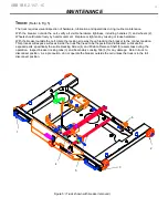
Page 18: ...ate the racking screw as though racking the breaker to the connect position This process will expose surfaces inside the truck that need to be inspected and lubricated Lubricate the exposed parts specifically the entire Racking Screw 4 and Position Release Shaft 5 assemblies during the operation Inspect breaker locking tabs 3 and Secondary Locking Tab 6 for any damage Return truck to disconnect po...

Page 19: ...ation will not sustain the voltage across the secondary Replace the breaker control wiring if the insulation fails during low frequency withstand voltage testing Replace the front cover before operation Verify the operation with 2 5 electrical operations in the Test position or with a remote power supply PRIMARY CIRCUIT ASSEMBLY Pole The primary circuit requires visual inspection of hardware low f...

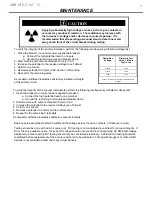
Page 20: ...nd turn off machine 6 Repeat for the remaining 5 terminals A successful withstand indicates satisfactory vacuum integrity CAUTION A Current energizes 52TC Applying abnormally high voltage across a pair of open contacts in vacuum may produce X radiation The radiation may increase with the increase in voltage and or decrease in contact spacing It is recommended that all operating personnel stand at ...

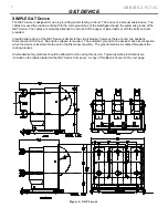
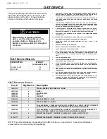
Page 21: ...ovided Insertion and racking of the G T Device is similar to the circuit breaker however there are only two positions Disconnect and Connect No position release is required The automatic ground on the device makes its connection when the device is inserted into the cell in the Disconnect position The ground remains in contact throughout the racking process All standard safety practices should be a...

Page 22: ... SET AND THE LONG SET ATTACHES TO THE UPPER TERMINAL SET 3 THIS DEVICE IS DESIGNED FOR USE WITH ONLY ONE SET OF CABLES AT TACHED TO A TERMINAL SET AT ANY GIVEN TIME EITHER THE UPPER TERMI NALS ARE GROUNDED THROUGH THEIR CABLE SET OR THE LOWER TERMI NALS ARE GROUNDED THROUGH THEIR CABLE SET 4 A POSITION STOP IS PROVIDED IN THE CONNECT POSITION AND THE DISCON NECT POSITION TO ASSURE THAT THE DEVICE ...

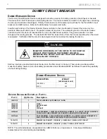
Page 23: ...INSERTION OR REMOVAL OF THIS DEVICE TO OR FROM THE CONNECT POSITION WHILE THE PRIMARY CIRCUIT IS ENERGIZED WILL RESULT IN AN ARC FAULT AND POSSIBLE PHYSICAL INJURY OR DEATH Kirk Key interlocks are provided to lock the device in the Disconnect or Connect These locks provide an added measure of safety however ALL other safety procedures and verifications MUST be followed to avoid the possibility of ...

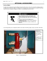
Page 24: ...s to protect the safety of personnel and equipment Always inspect lifting hook for signs of wear or damage before use Do not use a lifting hook that is damaged or worn The lifting device i e hoist wench should be suitably rated for lifting the breaker load Always refer to Fig 7 below for the proper installation of the lifting hook The chain type lifting hook is designed to attach to the breaker in...

Page 25: ...KING SCREW 8 COLLAR 9 POSITION RELEASE LEVER 10 HANDLE 11 CELL INTERLOCK TAB 12 TRUCK 13 WHEEL 14 POLE ASSEMBLY 15 PRIMARY CONTACT 16 OPERATION COUNTER 17 SHUTTER ACTUATOR ROLLER 13 15 17 7 8 9 10 11 16 6 4 5 1 2 3 Basic Breaker Layout APPENDIX A BASIC BREAKER LAYOUT APPENDICES All ADVAC breakers have the same basic layout regardless of rating or pole configuration 14 12 ...

Page 26: ...LOGUE DIGITS 1 3 CATALOGUE DIGIT 4 CATALOGUE DIGIT 5 WEIGHT approx lbs AA3 1 3 5 A B 1 2 410 lb AA3 1 3 5 A B 3 550 lb AA3 2 6 1 2 490 lb AA3 2 6 3 550 lb AA3 4 1 2 370 lb AA3 4 3 550 lb All ADVAC breakers of this style have the same basic dimensions i e pole spacing regardless of pole configuration ...

Page 27: ... DIGIT 4 CATALOG DIGIT 5 WEIGHT Approx lbs AF3 1 3 5 A B 1 2 370 AF3 4 1 2 330 750 MM FIXED RETROFIT MOUNT R All ADVAC breakers of this style have the same basic dimensions i e pole spacing mounting locations regardless of pole configuration Hole patterns do change dependent upon the ampacity of the breaker ...

Page 28: ...ABB IB 6 2 15 7 1C AssembledPole 15kV2000A50kA 15kV3000A40 50kA EmbeddedPoleP3 15kV 1200A 25 40kA EmbeddedPoleP2 15kV2000A25 40kA ADVAC Pole Assemblies and spacing APPENDIX B POLE ASSEMBLIES USED ON ADVAC ...

Page 29: ...ic characteristics for the CLOSE and OPEN coils used on the ADVAC breakers Resistance ranges may be used to identify the nominal voltage rating of a coil All coils are DC voltage coils AC power is rectified in the coil mounting assembly NOMINAL CONTROL VOLTAGE OF BREAKER VOLTAGE RANGE RESISTANCE RANGES W 24VDC 14 28 VDC 3 5 4 2 48VDC 28 56VDC 9 5 4 2 125VDC 120VAC 70 140VDC 104 127VAC 48 4 0 250VD...

Page 30: ...e The point to point diagram shows the physical connections and wire numbers used in the wiring harness FIXED MOUNT RETROFIT STANDARD WIRING The wiring scheme for the fixed mount breakers is exactly the same as that for the drawout breakers The only difference is that the terminations ending in the secondary disconnect plug on the drawout breakers are provided as un lugged wires for connection to ...

Page 31: ...ts will be available for use The point to point diagram shows the physical connections and wire numbers used in the wiring harness FIXED MOUNT RETROFIT OPTIONAL WIRING The wiring scheme for the fixed mount breakers is exactly the same as that for the drawout breakers The only difference is that the terminations ending in the secondary disconnect plug on the drawout breakers are provided as un lugg...

Page 32: ...G00 GCE0007249P0100 NA ISOFLEX TOPAS NB52 grease 961484 1 SWITHGEAR LINE UP BREAKER RELEASE MECHANISM AVAILABLE FROM ABB LAKE MARY ACCESSORIES Part Qty Breaker Description GCE0940084P0105 1 CHARGING MOTOR 120VAC 125VDC GCE0940084P0106 1 CHARGING MOTOR 240VAC 250VDC GCE0940084P0103 1 CHARGING MOTOR 48VDC 11142G00 1 OPERATION COUNTER ASSEMBLY 16008G00 1 ADVAC LABEL KIT 16016G30 1 FRONT PLATE ASSEMBL...

Page 33: ...4590P0115 1 OPEN COIL 125VDC GCE7004590P0116 1 OPEN COIL 250VDC GCE7004590P0113 1 OPEN COIL 48VDC GCE7004590P0111 1 OPEN COIL 24VDC 18069G10 1 UNDERVOLTAGE ASSEMBLY 125VDC 18069G20 1 UNDERVOLTAGE ASSEMBLY 250VDC 18069G30 1 UNDERVOLTAGE ASSEMBLY 48VDC 18069G40 1 UNDERVOLTAGE ASSEMBLY 120VAC 18069G50 1 UNDERVOLTAGE ASSEMBLY 240VAC GCE7004590P0105 1 2ND OPEN COIL ASSEMBLY 125VDC GCE7004590P0106 1 2ND...

Page 34: ...15 7 1C ABB Inc Circuit Breaker Technology Solutions 2300 Mechanicsville Highway Florence SC 29501 Toll free 1 877 SOS CBTS or 1 843 413 4700 Fax 1 843 413 4850 www abb com mediumvoltage IB 6 2 15 7 1C November 2005 ...

Reviews: