8
ABB IB 6.2.15.7-1C
T
EST
T
HROUGH
D
ISCONNECT
:
1. Perform visual inspection:
a. Verify Close/Open Indicator shows OPEN
b. Verify switchgear Door is CLOSED.
2. Actuate (push down) Position Release Lever (9) to begin racking from Test position
a. Begin racking in the COUNTER-CLOCKWISE direction
b. Release Position Release Lever once racking has begun (after approx. 1/2 turn)
c. Approx. four (4) revolutions (40mm) will move the breaker between the Test and Disconnect positions
•
The Test Position is indicated by a positive lock
•
Closing of the breaker is prevented between Disconnect and Test positions
•
Control power is unavailable in the Disconnect Position; shutters are closed.
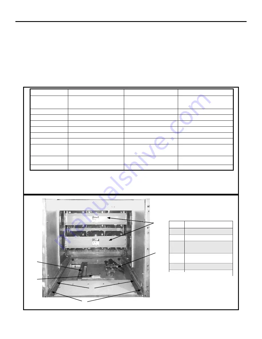
#
Description
A
COMPARTMENT SLOTS
B
GROUND BAR
C
INTERFERENCE
BLOCKING PLATE
D
SECONDARY
E
WHEEL RAILS
F
SHUTTERS
D
E
F
A
C
B
Figure 1: Basic Cell
Notes
:
A. Closed door racking is recommended between ALL positions.
DISCONNECT
TEST
CONNECT
Approximate Distance from
Disconnect
0 MM
0 REVOLUTIONS
0 INCHES
40 MM
4 REVOLUTIONS
1.57 INCHES
250 MM
25 REVOLUTIONS
9.84 INCHES
Manual Operation
YES
YES
NOT RECOMMENDED
Electrical Operation
NO
YES
YES
Control Power Available
NO
YES
YES
Shutter
CLOSED
CLOSED
OPEN
Primary Contacts Engaged
NO
NO
YES
Position Indication
POSITIVE LOCK & CELL DECAL
POSITIVE LOCK & CELL DECAL
POSITIVE LOCK & CELL DECAL
Interlocks
INTERFERENCE BLOCKING PREVENTS
INSERTION
RELEASE LEVER
RELEASE LEVER
CLOSING PREVENTED BETWEEN
POSITIONS
CLOSING PREVENTED BETWEEN
POSITIONS
RELEASE LEVER
Requirements To Rack
breaker from Position
BREAKER OPEN
POSITION RELEASE LEVER ACTUATED
BREAKER OPEN
POSITION RELEASE LEVER ACTUATED
BREAKER OPEN
POSITION RELEASE LEVER ACTUATED
Notes
A, B
A
A
Table 1: Summary Racking Data
INSERTION AND REMOVAL


