Parameters 277
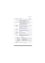
Selects the source for quick brake chopper on/off control.
0 = Brake chopper IGBT pulses are cut off
1 = Normal brake chopper IGBT modulation.
This parameter can be used to program the chopper
control to function only when the supply is missing from a
drive with a regenerative supply unit.
Off
0.
0
On
1.
1
Source selection (see
on
page
-
Defines the thermal time constant of the brake resistor for
overload protection.
0 s
0…10000 s
Brake resistor thermal time constant.
1 = 1 s
Defines the maximum continuous braking power of the
resistor (in kW) which will raise the resistor temperature to
the maximum allowed value. The value is used in the
overload protection.
0.00 kW
0.00…10000.00 kW
Maximum continuous braking power.
1 = 1 kW
Defines the resistance value of the brake resistor. The
value is used for brake chopper protection.
0.0 ohm
0.0…1000.0 ohm
Brake resistor resistance value.
1 = 1 ohm
Selects the fault limit for the brake resistor temperature
protection function. When the limit is exceeded, the drive
trips on fault
The value is given in percent of the temperature the
resistor reaches when loaded with the power defined by
parameter
105%
0…150%
Brake resistor temperature fault limit.
1 = 1%
Selects the warning limit for the brake resistor temperature
protection function. When the limit is exceeded, the drive
generates a
warning.
The value is given in percent of the temperature the
resistor reaches when loaded with the power defined by
parameter
95%
0…150%
Brake resistor temperature warning limit.
1 = 1%
45
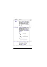
Settings for the energy saving calculators.
See also section
(page
).
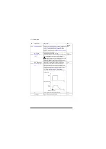
Displays the energy saved in GWh compared to direct-on-
line motor connection. This parameter is incremented
when
rolls over.
This parameter is read-only (see parameter
).
-
0…65535 GWh
Energy savings in GWh.
1 = 1 GWh
No.
Name/Value
Description
Def/
FbEq16
Summary of Contents for ACS880 ESP
Page 1: ...ABB industrial drives Firmware manual ACS880 PCP ESP control program ...
Page 4: ......
Page 28: ...28 PCP ESP control start up ...
Page 30: ...30 Using the control panel ...
Page 94: ...94 Standard programposi features ...
Page 100: ...100 Default control connections ...
Page 360: ...360 Parameters ...
Page 436: ...436 Fault tracing ...
Page 486: ...486 Control chain diagrams ...
Page 492: ...492 Appendix ESP with step up transformer and sine filter ...
Page 494: ...Contact us www abb com drives www abb com drivespartners 3AXD50000016186 Rev B EN 2015 10 27 ...


