■
Connection procedure
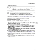
WARNING!
Obey the safety instructions of the drive. If you ignore them, injury or death,
or damage to the equipment can occur. If you are not a qualified electrical
professional, do not do installation or maintenance work.
WARNING!
Apply grease to stripped aluminum conductors before attaching them to non-coated
aluminum cable lugs. Obey the grease manufacturer’s instructions.
Aluminum-aluminum contact can cause oxidation in the contact surfaces.
1. Stop the drive and do the steps in section
Electrical safety precautions (page 27)
before
you start the work.
2. Open the door of the DC feeder cubicle and remove the shrouding.
3. Lead the power cables into the cubicle.
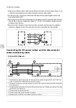
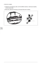
4. Ground the power cable shields 360 degrees at the cable entry (a).
5. Cut the power cables to a suitable length. Strip the cable and conductor ends, and install
the cable lugs at the end of the conductors. Use bolt M12 for the DC busbar connection
and M10 for the PE busbar connection.
6. Connect the conductors to appropriate terminals. Tighten to 70 N·m.
Note: The image below shows the connection for a two-string version of the unit. See
the delivery-specific circuit diagrams for the number of strings and actual connections
needed in the delivery.
7. Twist the cable shields into bundles and connect them to the protective grounding busbar
(PE) of the cabinet (b). Tighten to 42 N·m.
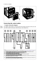
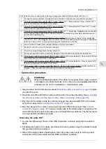
8. Lead the monitoring cable for the energy storage disconnector into the cubicle. For more
information on the cable routing, grounding and connections, see
9. If you do not need to install other cables, refit the shrouding removed earlier and close
the cubicle doors.
10. At the energy storage, connect the cables according to the instructions of the energy
storage manufacturer.
Electrical installation 31
11
Summary of Contents for ACS880-7107LC DC
Page 1: ... ABB INDUSTRIAL DRIVES ACS880 7107LC DC feeder unit Hardware manual ...
Page 2: ......
Page 4: ......
Page 8: ...8 ...
Page 12: ...12 ...
Page 22: ...22 ...
Page 36: ...36 ...
Page 40: ...40 ...
Page 44: ...44 ...
Page 50: ...50 ...
Page 52: ...52 ...
Page 55: ...Terminal and cable entry data for the power cables Technical data 55 ...

