


Draining the internal cooling circuit
The modules in each cubicle can be drained through the drain valves without draining the
whole internal cooling circuit.
WARNING!
Hot, pressurized coolant can be present in the cooling circuit. Do not work on the
cooling circuit before the pressure is released by stopping the pumps and draining
coolant.
1. Attach hoses to each drain valve in the cubicle to be drained. Lead the hoses into a
suitable container. Make sure the ends of the hoses are not immersed in coolant at any
point so that air can displace the coolant in the system.
2. Open the drain valves. Wait until all coolant has drained.
Note:
Draining coolant into the sewer system is not allowed.
3. If required, dry the piping with compressed oil-free air of less than 6 bar.
4. If the drive is to be stored in temperatures below 0 °C (32 °F),
• dry the cooling circuit with air,
• fill the cooling circuit with coolant specified under
Coolant specification (page 84)
• drain the cooling circuit again.
Maintenance intervals
As a general rule, the quality of the coolant should be checked at intervals of two years.
This can be done by distributors of Antifrogen® L (see
) if a 250 milliliter
sample is provided.
Technical data
■
Coolant specification
Coolant type
Antifrogen® L (by Clariant International Ltd,
) 25% or 50% mixture, available
from Clariant distributors and ABB Service representatives.
Note:
Do not dilute the coolant. It is ready to use.
Antifrogen® L 25% mixture is usable in storage temperatures down to -16 °C (3.2 °F).
Antifrogen® L 50% mixture is usable in storage temperatures down to -40 °C (-40 °F).
Note that operation below 0 °C (32 °F) is not allowed regardless of the freezing point of the
coolant.
WARNING!
The warranty does not cover damage occurring from use of improper coolant.
■
Temperature limits
Ambient temperature:
See the technical data of the drive/unit.
84 Internal cooling circuit
Summary of Contents for ACS880-607LC
Page 1: ... ABB INDUSTRIAL DRIVES ACS880 607LC 3 phase dynamic brake units Hardware manual ...
Page 2: ......
Page 4: ......
Page 10: ...10 ...
Page 30: ...30 ...
Page 34: ...34 ...
Page 46: ...46 ...
Page 56: ...56 ...
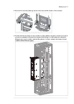
Page 72: ...7 After the module has drained disconnect the piping from the module 72 Maintenance ...
Page 88: ...88 ...
Page 95: ... Bottom entry and exit of cables Dimensions in mm 1 mm 0 0394 in Technical data 95 ...
Page 96: ...Dimensions in mm 1 mm 0 0394 in 96 Technical data ...
Page 97: ... Top entry and exit of cables Dimensions in mm 1 mm 0 0394 in Technical data 97 ...
Page 104: ...Brake unit with bottom exit Dimensions in mm 1 mm 0 0394 in 104 Dimension drawings ...
Page 105: ...Brake unit with top exit Dimensions in mm 1 mm 0 0394 in Dimension drawings 105 ...
Page 106: ...Bottom Top Dimensions in mm 1 mm 0 0394 in 106 Dimension drawings ...