


Figure
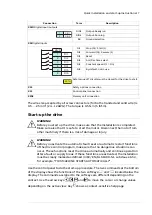
Task (input cables)
Step
-
Ground the input cable shields (if present) 360 degrees at the cabinet entry.
1
-
Connect the twisted shields of the input cables and separate ground cable (if
present) to the cabinet grounding busbar.
2
O
3
• Step drill carefully sufficiently big holes to the clear plastic entry shroud for the
cables to the connected. Align the holes in the vertical direction according to
the alignment holes in the shroud. Smooth the hole edges.
• Remove the plastic sheeting from both sides of the shroud.
• Attach the cables firmly to the cabinet frame to prevent chafing against the hole
edges.
Q
Put the conductors of the input cables through the drilled holes in the clear plastic
shroud.
4
R
Connect the input power cable conductors to the L1/U1, L2/V1 and L3/W1 connection
busbars.
5
S
Move the entry clear plastic shroud along input cables to its final position. Install
the front clear plastic shroud and upper front cover. Remove the cardboard protect-
ive covering from the drive module air outlet.
6
T
Cut the hole for the clear plastic entry shroud in the side clear plastic shroud. Install
the side and top clear plastic shrouds to the drive module.
7
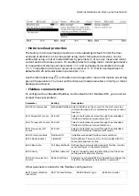
Connect the control cables
See figure U in chapter
Step-by-step drawings for an installation example (page 31)
.
1.
Disconnect the control panel cable from connector X13 on the control unit.
2.
Loosen the mounting screws of the control panel holder and take the holder off.
3.
Install the control cable grounding clamp plate to the control unit.
4.
Connect the power supply, BGDR and fiber optic cables to the control unit.
5.
Attach the control unit, for example, to a DIN rail.
6.
Connect the power supply and BGDR cables to the drive module ZPOW and BGDR
connrctors. Connect the fiber optic cables to V10 and V11 connectors.
7.
Ground the outer shields of all external control cables 360° at the cabinet entry.
8.
Ground the pair-cable shields of external control cables to a grounding clamp
below the control unit. Leave the other end of the shields unconnected or ground
them indirectly via a high-frequency capacitor with a few nanofarads, eg, 3.3 nF
/ 630 V.
9.
Connect the conductors to the appropriate connectors of the control unit.
10. Wire the optional modules if included in the delivery.
11. Connect the control panel cable to connector X13.
12. Put the control panel holder on the control unit. Put the control panel to the recess
if removed.
■
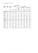
Default I/O connections
The default I/O connections of the Factory macro of the ACS880 primary control
program are shown below.
Quick installation and start-up instructions 15
Summary of Contents for ACS880-04F
Page 1: ...ABB INDUSTRIAL DRIVES ACS880 04F drive modules Quick installation and start up guide...
Page 2: ......
Page 4: ......
Page 6: ...6...


