CONTROL SYSTEM
PRODUCT
ACS1000W
DOCUMENT KIND
User manual
DOCUMENT ID.
3BHS213400 E01
REV.
J
LANG.
en
PAGE
4.2.2.2. Parameters
The control system is configured, customized, and tuned with a set of application
parameters. The application parameters are organized in functional groups and
have factory-set default values. The default parameter values are adjusted during
commissioning to the specific application of the drive in order to activate the
specific control, monitoring and protection functions for the driven process, and
to define the signals and data transferred between drive and external equipment.
For more information on the parameters for signal allocation, signal type
selection, signal inversion, scaling, and filtering, see
“Appendix G
-
Signal and parameter table”.
4.2.2.3. Main circuit breaker
The main circuit breaker (MCB) is an important switching and protection device of
the drive system. Therefore it must only be controlled and monitored by the drive.
For more information, see:
–
“Input circuit breaker engineering guideline” (3BHS104785 E01)
–
Main circuit breaker protection device
4.2.2.4. Direct torque control
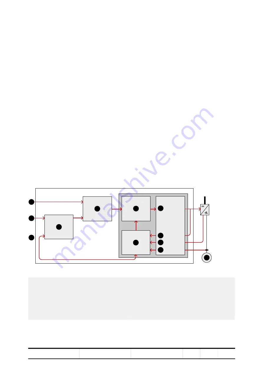
The speed and torque of the motor is controlled by DTC (Direct Torque Control).
DTC provides accurate speed and torque control, and high dynamic speed
response.
Figure 4
-
5 Direct torque control
Switching of the semiconductors in the inverter is directly controlled in accordance
with the motor core variables flux and torque.
1) Torque reference
2) Speed reference
3) Actual reference
4) Speed controller
5) Torque reference controller
6) Torque-flux comparator
7) Motor model
8) Switching logic
9) Switch positions
10) Voltage
11) Current
12) Motor
1
2
3
4
5
6
7
8
9
10
11
12


