background image

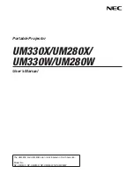
Designated Remote control shall be compatible with specific motorized cart

Model-1&Model-2

Model-3&Model-4

OR

ON

1

2

3

4

5

6

ECE

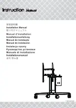
1.Please find out the PIN code on the 

sticker attached on the lift column of the 

stand.

3.Open the battery cover of the

handset,there is a 6-Digit DIP

SWITCH inside. 

4.Make sure the Setting of the

DIP SWITCH is the same as  

the PIN code showing on the

PIN code sticker.

RF Remote Control Setting

2.The PIN code can be also found out 

on the control box.

2

1

ON

1

2

3

4

5

6

ECE

Remote controller 

code label

Tilt Downward only 

Tilt Downward 

&

LIFT downward (both)

Tilt Upward 

LIFT Upward (both)

LIFT Downward only

LIFT Upward only 

Tilt Upward only 

Tilt Downward only 

LIFT Downward only

LIFT Upward only

Tilt Upward only

LIFT Downward only

LIFT Upward only 

LIFT Downward only

LIFT Upward only

10

Summary of Contents for CDT861M-NEW

Page 1: ...T78CPM8610101B v1...

Page 2: ...tions Caution EN 1 Veuillez lire enti rement ce manuel et en suivre attentivement les instructions avant l installation 2 Le fabricant ne sera tenu l galement responsable d aucun dommage l quipement o...

Page 3: ...nte se reserva el derecho de cambiar el dise o sin previo aviso 10 Consulte el manual en ingl s si tiene alguna duda acerca de las condiciones ES 2 F F F F PL Ostrze enie 1 Aby zapewni bezpiecze stwo...

Page 4: ...3 4 5 6 7 8 2 9 10 F F F F 1 Per garantire la sicurezza leggere attentamente questo manuale prima di effettuare l installazione e seguire le istruzioni qui contenute Conservare questo manuale in un l...

Page 5: ...e Werkzeuge Herramientas necesarias Ferramentas necess rias Potrzebne narz dzia Strumenti necessari Verktyg som kr vs Enclosed Parts 6 mm 5 mm A 1 A 2 B D E F G H 1 H 2 N P Q S 1 S 2 4 I OR C 2 J M L...

Page 6: ...t Height Adjust Range Model Name Model 1 2 3 4 M4 M5 M6 M8 Mounting pattern Screw Type Material Dimension 0 90 0 or 90 500mm 19 69 80 Model 1 Model 2 Model 3 Model 4 120 kg 264 55 lbs 800mmX600mm W131...

Page 7: ...H 2 L 6mm H 1 5mm D B A K 6...

Page 8: ...Q N Remote Controller Holder S 1 S 2 OR 7 H 1 I I B 1 5mm Model 3 Model 4 B 2 A Model 1 Model 2...

Page 9: ...F C G M Make sure mount bracket being upright before display to be installed 8...

Page 10: ...If tray module available If tray module available 5mm 5mm Model 1 Model 3 only Model 1 Model 3 only J 9 2 4mm 1 J 3 Tighten 4 E Hook...

Page 11: ...the Setting of the DIP SWITCH is the same as the PIN code showing on the PIN code sticker RF Remote Control Setting 2 The PIN code can be also found out on the control box 2 1 ON 1 2 3 4 5 6 ECE Remot...

Page 12: ...fuse box Connect the power cord Repeat Step 3 to see if all moves normal Specs on Fuse Voltage 10A Length 20 mm 5 Make sure designated trouble shooting has to be conducted by qualified technician Sha...

Reviews: