background image

Aaton

Video

53

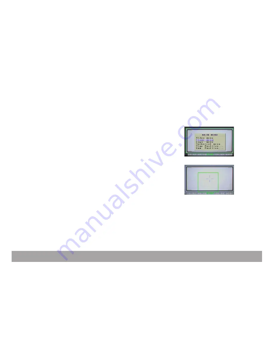
4.2 Frame Menu

•  The VHR can insert four (4) different frames in the video image. Each frame 

can  be  electronically  set  in  size  and  position  to  perfectly  match  the  camera 

viewing screen markings. The color and transparency of each frame can be in-

dividually set. The area outside the frame can also be filled with a chosen color 

and darkened or brightened.   

• From the main 

Video menu

, use the” down” key to select the 

Frame sub-

menu

 and press the “right” key to enter. You can deactivate the inserted frame 

by selecting 

OFF

 in the line frame. If you select 

ON

, you have the choice of 

four different frames labeled frame 1, 2, 3 and 4. Each frame will have to be 

set individually. Use the “up” and “down” keys to move to the line frame color 

and press the “right” key to access the RGB parameters of the selected frame. 

Play with the RGB values to modify the frame color then press the “exit” key to 

return to the 

Frame menu

• Use the “up” or “down” keys to select the sub-menu 

Frame top left

 press the 

“right” key to enter and modify the “top and left frame” marking position using 

the “up”, “down”, “left” and “Right” keys. Press the “exit” key to return to the 

Frame menu

• Proceed in the same way to modify the position of the 

Bottom

 and 

Right


lines of the frame markings. With no restriction, the inserted frame can be set 

in size and position to match the viewing screen layout but it can also be used 

to outline an object in the picture during a product shot.

Summary of Contents for Penelope

Page 1: ...penelope by Aaton User s guide version V1 1 December 2008 Aaton 35mm motion picture camera 2 3 Perf Aaton ...

Page 2: ...p 16 Power the video VHR on p 16 Power the camera and video off p 16 Set key p 16 The TEST mode p 17 Adjusting the Aatonite Glow p 17 Display colors camera status p 18 Warning messages p 19 Gate position p 19 Magazine top locking lever p 19 Magazine footage adjustment p 19 Feet or meters setting p 20 Magazine footage counter lock p 20 Video gain Direct access control panel p 20 2 Camera body 2 1 L...

Page 3: ...viewing horizon p 26 Adjusting the diopter p 26 The eyepiece shutter p 26 Viewing screen p 26 Changing the viewing screen p 27 Adjusting the viewing screen p 27 2 3 The variable shutter Concept p 28 Adjusting the shutter p 28 2 4 Film gate and pulldown claw Adjusting the pitch p 30 The side pressure bar p 30 The film gate p 30 2 5 Camera power Installing the batteries on the camera p 31 Charging t...

Page 4: ...p 35 Aatoncode Timecode reading p 35 ISO setting p 36 Camera preset SYNC speed p 36 Camera variable VAR speed p 37 Adjusting the battery warning levels p 37 Low battery alerts p 38 LCDs contrast adjustment p 39 Lemo 2 connector modes p 39 2 8 Accessible settings on the cameraman side p 40 3 The magazine 3 1 Concept p 43 3 2 Pressure plates system The gate plate p 43 The picture plate p 43 ...

Page 5: ...deo assist VHR 4 1 Video Menu p 51 Gain Output Color temp Saturation Color Bars outputing User color Temp p 52 4 2 Frame Menu p 53 4 3 Logo p 54 4 4 Technical Menu p 55 TimeCode menu p 55 Font Menu p 55 Auto Power Off p 56 VITC Position p 56 Time Cam position p 56 5 Technical specifications Connectors p 58 Viewing screens list p 60 ...

Page 6: ...General overview ...

Page 7: ... LEMO 2 connector Arri rosette Video VHR iris ring Video housing Top rod holder To adjust the image horizon To adjust the tension of the eyepiece swivel Eyepiece heating cable connector Lock ring for 35mm PL mounted lenses Start Stop cable connector For accessories equipped with Arri rosette To adjust the video iris aperture Protects the CCD unit To install a rod 15 15 8 or 19mm ...

Page 8: ...agazine upper top lever Fastens the upper on board battery Provide 12V Start and ground for accessories Used to connect USB key Provides 12V Start Sync pulse and ground for accessories Used to release the magazine from the camera body Timecode communication Removable gate 2 Perf or 3 Perf Used to start and stop the camera Used to secure the magazine on the camera body A4 1 2 3 4 5 6 7 8 9 ...

Page 9: ...tors Fastens the upper on board battery To start and stop the camera Provide power and composite video signal for MiniMonitors Quick camera parameters settings Accurate claw pulldown stroke adjustment To adjust the video iris aperture Provide video output To remove the magazine from the camera body Provides 12V Start Sync pulse and ground for accessories To lock the Ethernet cable when connected F...

Page 10: ...r battery locking screw Provide power and composite video signal for MiniMonitors Quick camera parameters settings Displays camera and video parameters Allows access to camera and video adjustments For camera and computer communication under cover Provide video output Provides 12V Start Sync pulse and ground for accessories Fastens the lower on board battery To lock the Ethernet cable when connect...

Page 11: ...h the setup menu and direct access to video Gain Control To position video inserted characters and setup inserted frame lines To exit setup menu To select functions To access the video setup menu displayed on monitor set vid To access the frame store and image comparison function To access the TimeCode menu To turn off and on both camera and video To access the camera technical menu To access sync...

Page 12: ...splay key Cameraman LCD display Middle display key Upper display key Start Stop button To lock unlock magazine door To check magazine remaining footage To lock unlock magazine door Loop size adjustment while loading the mag To modify camera parameters Displays camera speed and magazine remaining footage To modify camera parameters To modify camera parameters To start or stop the camera ...

Page 13: ...ce Video gain Lower battery level Upper battery level LCD display Cameraman side 10 9 8 7 6 5 1 2 3 4 1 3 2 Symbols blink error magazine upper lock or gate Selected speed mode Synch or Variable Footage in feet or meters Magazine remaining running time Hour minute seconde J shows an external TC jam Selected ISO exposure for Timecode 5600 K 3200 K and manual adjustment Current gain setting Lower bat...

Page 14: ...agazine upper lock lever Collimation cap Viewing friction screw Tape hook To install accessories brackets Variable shutter tool Pitch control tool To secure the magazine on the camera body To access ground glass collimation adjustment To adjust the viewfinder friction To attach a measurement tape ...

Page 15: ...1 Getting started ...

Page 16: ...ss the On Off key A window appears on the LCD screen Hold the On Off key Two bargraph timers start counting down faster for the Video and slower for the Camera This allows you to power down the Video without powering down the camera The Set key The Set key allows you to access the camera s settings While pressing the Set key a window appears for a few seconds allowing you to access the desired par...

Page 17: ... frame press the middle display key B located on the cameraman side When you need to leave the TEST mode press the Start Stop button again for 3 to 4 seconds Adjusting the Aatonite glow Penelope features a viewing screen with illuminated markings referred to as Aatonite The level of illumination is user adjustable using the middle B and upper C display keys located on the cameraman side The config...

Page 18: ... tion allows the cameraman and camera crew to be immediatly informed of the camera s status Pale blue screen camera is in STANDBY mode Orange screen camera is in RUN mode but has not reached the selected speed Green screen camera is in RUN mode and sync Purple screen end of film Red screen problem detected out of phase film jam ...

Page 19: ... reinstall it Magazine upper lock lever The magazine top locking lever located on top of the camera body insures the magazine s proper positioning It is equipped with a position sensor which does not allow the camera to start if this lever is unlocked If it is the message MAG NOT LOCKED is displayed Lock the lever and start the camera Magazine footage adjustment Press the Set key then the Mag key ...

Page 20: ...ine footage counter lock Lock the magazine footage counter A located on the mag door while the camera is running Video gain Direct access control panel All of the video adjustments are accessible through the VIDEO page The video gain can also be adjusted through the control panel Press the up or down key to change the video gain The adjustment range is 10dB to 12dB in 1dB steps A4 ...

Page 21: ...Aaton Getting started 21 ...

Page 22: ...2 Camera body ...

Page 23: ...into the camera port so that its flanges rest evenly against the lens seat Tighten the locking ring by turning it clockwise until the lens is secured and the locking ring is set firmly Make sure the locking ring is tight enough so that it cannot be inadvertantly unlocked Flange focal distance Refers to the critical distance from the lens seat to the film plane With the PL port the precise FFD of P...

Page 24: ...2 socket located on the camera front body near the lens mount Note the Penelope viewfinder is equipped with a mini Arri PL port which makes it compatible with a wide range of Arri viewfinder accessories Attaching the finder extension In order to use an extension finder first remove the eyepiece by rotating the eyepiece locking ring A clockwise until it reaches its stop and gently pull the eyepiece...

Page 25: ...moderate amount of pressure When using a finder extension tension should be increased to support the additional weight To adjust the tension of the swivel rotate the knurled screw C To increase the tension of the eyepiece swivel rotate the knurled screw clockwise to decrease the tension rotate the knurled screw counter clockwise Adjusting the viewing horizon If the rotation of the image seen throu...

Page 26: ...ickly recall your particular setting when more than one person will be looking through the viewfinder The eyepiece shutter To prevent light leakage through the viewfinder the eyepiece shutter must be closed any time the camera is running film and the operator s eye is away from the viewfinder Locate the small silver lever located on the eyecup ring F To close or open the eyepiece shutter push this...

Page 27: ...he holder aligning the two white marks of both holder and screen Proceed as before with a piece of Post it on your finger Adjusting the viewing screen The image focus on the viewing screen or ground glass should match the lens barrel focus mark and the focus on the film Before adjusting the viewing screen be certain that the flange focal distance of the camera is set according to the manufacturer ...

Page 28: ...oll bar while filming NTSC broadcast monitor at 24 fps Adjusting the shutter To adjust the shutter opening unscrew the shutter tool marked Sh located in the hollow at the rear of the camera s carrying handle Make sure that the bat tery is off the camera and remove the port cap Locate the tool guiding hole to the lower right of the inside lens holder Gently rotate the shutter at its base with your ...

Page 29: ... clockwise will increase the opening When setting the opening to 172 8 150 or 144 a shutter blade indicating these settings will be visible from behind the left edge of the mirror Make sure the white line to the immediate right of the 172 8 150 and 144 markings meet the left edge of the mirror When the adjustment is complete remove the tool and store it back in the hollow of the carrying handle Br...

Page 30: ...mera The camera will run with a clicking noise due to the perf being hit by the claw Turn the tool clockwise until you reach a more pleasant noise like a loud purring Once you reach the proper setting it is recommen ded to turn the tool counter clockwise approximately 20º to accomodate any variation of the film pitch that occures between different film stocks or under humid or hotweather condition...

Page 31: ...he rear of the camera body on the assistant side In order to install loosen the blue knurled screw A approximately four or five turns Push the batteries evenly onto the XLR connectors of the camera body When snug tighten the knurled screws onto the battery tabs to hold each in place When running Aatoncode timecode think about having a fresh battery on hand Even a low battery below 10V has enough v...

Page 32: ...hese chargers were most likely rated for the lower amperage batte ries of that time and will consistently undercharge the higher rated NIMH cells of today Other power options Since Penelope power inputs are the standard 4 pin XLR type a great variety of 12 to 14 VDC sources can be used to power the camera This includes AC power supplies battery blocks Lithium cells and car batteries Get into the h...

Page 33: ...le preset speeds are 6 12 18 20 23 98 24 25 29 97 30 33 33 36 40 48 and 50 fps The sync key allows for quick access to these fre quently used speeds If any other speed is desired or if the camera speed must match the frequen cy of a monitor to eliminate a rolling bar the var key should be employed The specific speed selector enables the body to run at any speed between 1 and 50 in 001 frame steps ...

Page 34: ...and compromise image registration Aaton urges to avoid such usage at all cost and will not be responsible for the resulting damages that will occur This top speed cap of 50 fps has been designated by Aaton because it is the limit at which the camera can run safely without any adverse effects to its mechanics 2 7 LCD control panel and jog wheel assistant side Penelope utilizes a straightforward and...

Page 35: ...atoncode timecode reading As a standard feature Penelope is equipped with the capability of recording AatonCode in camera timecode Timecode information is exposed onto the film by optical projection of seven micro diodes into the gate These micro diodes flash rapidly to form the code as the film rolls through the gate between exposures If AatonCode has been initialized in the camera you can see it...

Page 36: ...wheel or by toggling the up or down key If the ISO selector is adjusted while the camera is in TEST or RUN mode the correction will not take place until the next camera start Camera preset SYNC speed The default mode of the control panel will automatically display the camera speed selection whether it be in SYNC or VAR mode when the camera is powered but not running When the camera is turned on th...

Page 37: ... a preset level The thresholds set for Batt 1 and Batt 2 do not overide the cameras default minimum levels To adjust these levels press set key then sech key to open the technical menu Select the Bat Alert sub menu and press right key to access Select a value between 10 8V and 14V for battery 1 by rotating the jog wheel or by toggling the top and down keys Follow the same procedure to adjust batte...

Page 38: ... on both LCD screens and a red LED blinks in the camera viewfinder The camera continues to run properly and Low is displayed in front of the battery icon If both batteries are too low the alert is displayed on both assistant and came raman screens Low batt 1 Low batt 2 Low power Low power cameraman LCD ...

Page 39: ... procedure Press the set or exit keys to validate your selection Lemo connectors modes Penelope has two start stop modes for accessories with Lemo connectors IMPULSION for accessories using pulse signal PERMANENT for Aaton wooden handgrip Run switches and cables from existing Aaton cameras 35 III Xtera XTRProd etc To choose one of these modes press set key then tech key to open the technical menu ...

Page 40: ...evel see Getting started You can also modify the camera running speed only in SYNC mode and the magazine footage Press the lower 1 display key then the middle 2 or upper 3 display key to select SPEED or MAG modes When selected press the lower 1 display key The selected parameter starts to blink Use the middle 2 or upper 3 display key to modify the value Press the lower 1 display key to validate 3 ...

Page 41: ...Aaton Camera body 41 ...

Page 42: ...3 Magazine ...

Page 43: ...footage can also be adjusted in the camera setting see Getting started chap ter The magazine handles up to 400 ft 122m loads of 35mm film stock maximum 3 2 Pressure plates system The gate plate A The long plate called the gate plate is located at the front of the nose of the magazine When the loaded magazine is installed on the camera body its main function is to stabilize the film as the claw eng...

Page 44: ...n be done in the daylight prepare the mag to receive the film Place the magazine on a table its throat facing left Turn the mechanical footage counter A clockwise until it locks in place Unfasten the two blue mag locking levers B turning them counter clockwise Open the door Check the magazine loading system Then put the magazine in a dark room or changing bag A A B B C D E F G G H H 1 1 2 2 3 3 4 ...

Page 45: ... film from its can and bag Place the film on the feed spindle with its winds clockwise and press the center of the core lock mechanism to lock the core in place A Push the film head into the center slot B until it engages the inner sprocket wheel A B ...

Page 46: ... take up core holder clockwise making sure the film perforations engage the sprocket teeth When the film comes out of the sprocket assembly gently pull on it Pull approximately 20 cm 8 inches of film and insert it in the bottom slot until it meets the lower sprocket teeth ...

Page 47: ...t of the sprocket assembly B Continue to turn the take up core holder until the film reaches the bottom roller C Place a core on the take up side spindle press the center of the core holder to lock the core in place Fit the film end into the plastic take up core and wind on a few turns clockwise with the emulsion in Close the door A B C ...

Page 48: ...lling it up Push the loop release button and hold it pressed Turn the loop adjustment knob clockwise while pressing on it to shorten the loop size until the loop adjustment tool is held between the loop and the pressure plate Use the loop adjustment tool to determine the ideal loop size corresponding to approximately 37 visible perfs ...

Page 49: ...he aperture area with your right hand Make sure that the top of the nose of the mag is parallel to the camera as you guide the mag in place Push firmly and evenly until you feel and hear that the mag snaps against the aperture area Don t forget to lock the magazine by pushing the magazine upper lock lever Removing the magazine To remove the magazine situate yourself at the rear of the camera body ...

Page 50: ...4 Video ...

Page 51: ... is running STOP in green color when the camera is stopped 4 1 Video Menu Use the up or down keys to select the desired parameters Once selected enter the parameters setting with the left or right key and use the up and down keys to modify them then press the exit key to validate the data and return to the previous level The Video menu allows you to set up the following video image parameters Gain...

Page 52: ...id intense color while a less saturated image will appear more muted and grey With no satu ration at all the hue becomes a shade of grey Adjustment ranges from 0 to 200 Color Bars generates color bars which can be used to calibrate a moni tor User color temp this menu is activated if the Color temp menu is set to USER Use the left and right keys to select the three primary colors Red Green and Blu...

Page 53: ... frame 1 2 3 and 4 Each frame will have to be set individually Use the up and down keys to move to the line frame color and press the right key to access the RGB parameters of the selected frame Play with the RGB values to modify the frame color then press the exit key to return to the Frame menu Use the up or down keys to select the sub menu Frame top left press the right key to enter and modify ...

Page 54: ...odify the RGB parameters of the frame outside area Darkening and brightening this area can be done by modifying the transparency parameter 4 3 Logo The VHR allows you to insert a Logo in the monitor picture This Logo can be created and uploaded in the VHR through a Lemo 5 Serial port cable From the Video menu use the down key to select the Logo sub menu and press the right key to enter Once the Lo...

Page 55: ...wer off of the VHR de lay to Power Off VITC video time code position and Parity Time Code Menu Time Code Off On allows you to choose to insert ON or not OFF AatonCode information which consists of Time Date and Camera equipment number ID Use the left and right keys to proceed Font Menu Font allows you to choose the font of the displayed information Two fonts are available 0 and 1 Use the left and ...

Page 56: ... you to choose the position of the VITC lines Choice from 10 to 23 in PAL Aaton recommends line 19 or from 13 and 19 in NTSC Parity allows you to select the parity of the VITC lines ODD and EVEN Make sure that your Post Production tools run properly with the selected value Time Cam position The VHR inserts the camera speed and magazine footage as well as time code information in the video image Th...

Page 57: ...5 Technical specifications ...

Page 58: ...iptions from user s side LEMO 2 On Off 1 Ground 2 Start Fischer 2 Heating cable 1 Ground 2 Batt LEMO 5 TimeCode 1 Ground 2 SMPTE In 3 Ascii In out 4 Not used 5 Not used LEMO 6 Power 1 Ground 2 Not used 3 Not used 4 batt 5 Not used 6 Start 1 2 1 2 1 2 3 4 5 1 2 3 4 5 6 ...

Page 59: ...s side LEMO 8 Speed Controllers 1 Ground 2 Top Tour one pulse per frame 3 Ascii In Out 4 Batt 5 Tachy out 6 Start 7 Tachy in 8 Ground XLR 4 Power In 1 Ground 2 Not used 3 4 linked Batt 1 2 3 4 5 6 7 8 1 2 3 4 Fischer 4 Video output 1 Ground 2 Video ground 3 Video output 4 Batt 1 2 3 4 ...

Page 60: ...nsmitted 16 9 1 85 2 35 1 78 Transmitted 16 9 offset AATON Penelope 2 Perf 1 78 AATON Penelope 2 Perf 2 35 1 78 HDTV 2 35 1 78 HDTV AATON Penelope 3 Perf 1 78 TV Safe AATON Penelope 3 Perf 2 35 2 35 Centric 1 78 TV Safe Ref 33 230 20 Ref 33 230 21 Ref 33 230 22 Ref 33 230 23 Ref 33 230 25 Ref 33 230 26 Ref 33 230 27 Ref 33 230 28 Ref 33 230 29 2 Perf S35 centered 3 Perf ANSI S35 centered ...

Reviews: