background image

Installing MX-ONE

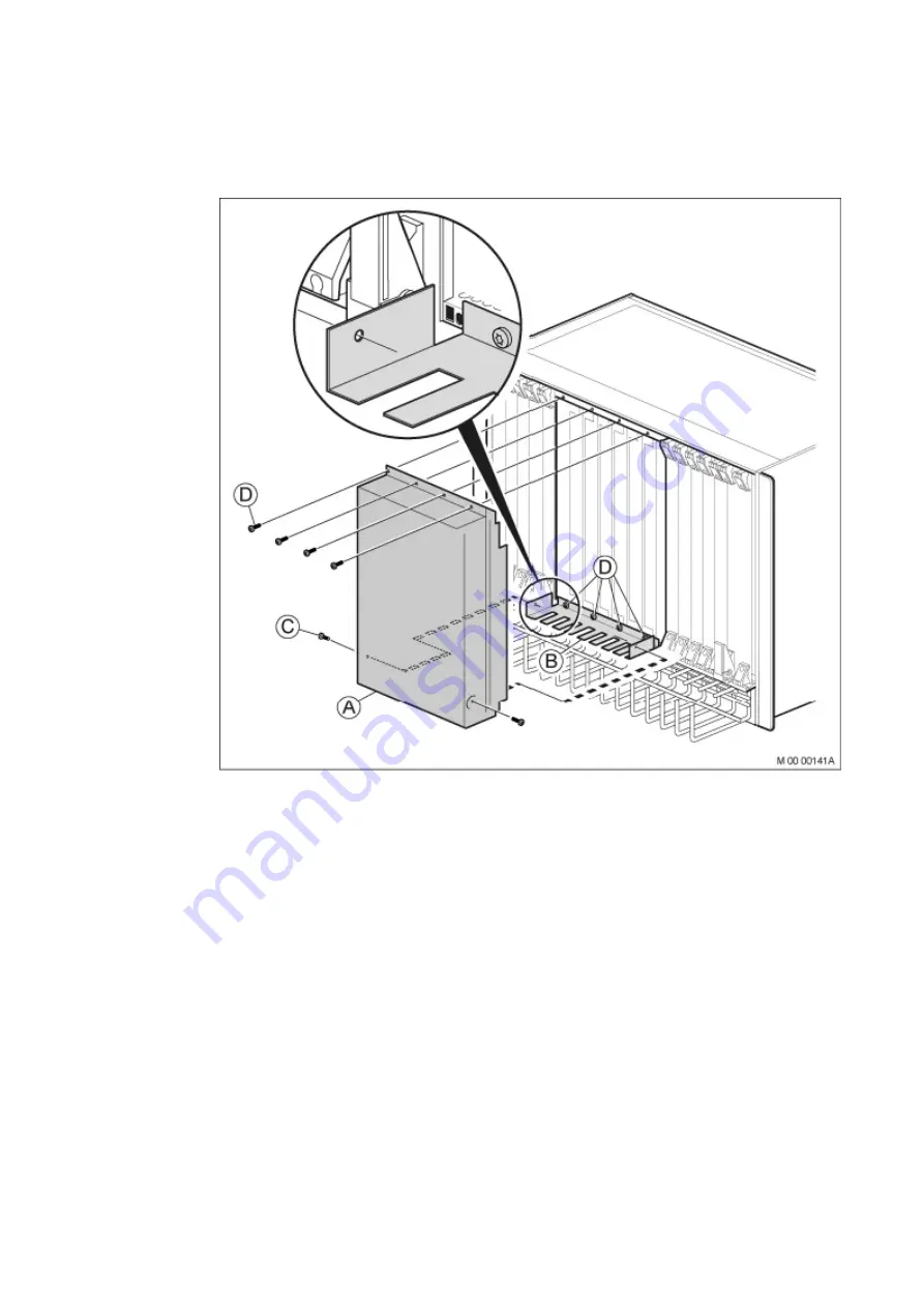
Figure 47

Installing the Board Cover

Note:

The board cover must be installed to fulfill the EMC requirement.

1

Fasten the finger plate (B) using four screws (D), Page 64 .

2

Fasten the board cover (A) above the finger plate using four screws (D) on
the top part, and the two screws (C) on the bottom part, Page 64 .

3

Install board cover on the other subrack in the same way.

4.9

Installing the Fan Unit

This section describes the installation of fan unit and upper air plate in the
cabinet.

Note:

If only one subrack is to be installed the fan unit must be strapped for

being fed from only one DC/DC converter.

64

6/1531-ASP 113 01 Uen J2 2008-07-17

Summary of Contents for MX-ONE

Page 1: ...Installing MX ONE INSTALLATION INSTRUCTIONS...

Page 2: ...ithout the written permission of the copyright owner The contents of this document are subject to revision without notice due to continued progress in methodology design and manufacturing Aastra shall...

Page 3: ...al Positions in LBP22 13 2 11 Boards in Media Gateway Classic 14 2 12 Cables 17 2 13 Environmental Requirements 18 3 Installation Preparation 21 3 1 Tools 21 3 2 ESD Wrist Strap in Conjunction with Se...

Page 4: ...Fronts 109 5 8 Extension Cable Structure 110 6 Connection of External Cables 117 6 1 General 117 6 2 Line Lengths 117 6 3 Analog Extensions 118 6 4 Digital Extensions 119 6 5 Cordless Extensions 121...

Page 5: ...ion Test for MX ONE Telephony System 141 10 Mounting Side Plates Doors and Back Plate 143 10 1 Installing Panel 143 10 2 Installing the Side Plates 144 10 3 Installing the Cabinet Doors 147 10 4 Insta...

Page 6: ...Installing MX ONE 6 1531 ASP 113 01 Uen J2 2008 07 17...

Page 7: ...allation test These installation instructions describe the mounting and cabling of an exchange which has been fully equipped before the delivery to the installation site 1 2 Target Group The target gr...

Page 8: ...n must read and understand the safety instructions prior to installation see the description for SAFETY 1 3 4 Site Planning The MX ONE should be installed in a room prepared for the system For informa...

Page 9: ...ower units batteries subracks with extension boards fan units Media Gateways and servers The number of components and their location in the cabinet vary according to customer needs For an example of a...

Page 10: ...Installing MX ONE Figure 1 MX ONE Cabinets 4 6 1531 ASP 113 01 Uen J2 2008 07 17...

Page 11: ...48 V DC 4 7 2 C Battery 62 Ah 4 battery blocks BKB 201 003 2 425 x 264 x 280 82 48 V DC 6 10 8 AC DC Unit BZA 109 08 1 450 x 128 x 280 11 5 205 240 V AC 48 V DC 3 5 4 D AC DC Unit BZA 109 09 1 487 x...

Page 12: ...AC 1 not for BYB 501 K MX ONE Server BFJ 901 04 1 440 x 45 x 260 3 5 100 240 V AC 48 V DC 1 2 L MX ONE Compact SM BFJ 901 05 x 440 x 90 x 260 4 9 100 240 V AC 48 V DC 2 4 1 Varies according to custome...

Page 13: ...e 5 2 2 AC DC Power Unit The AC DC power unit converts the power input from the AC power supply network to DC output for the batteries and for the DC DC converters in the subracks Note Other versions...

Page 14: ...rter converts the batteries DC output to AC power for the Media Gateway and the servers The inverter is optional and can be replaced with other types of power backup solutions Aastra is not supplying...

Page 15: ...ic The subracks consist of the following parts A Subrack A upper subrack B Subrack B lower subrack C Boards D DC DC unit board E Board cover when needed F Cable chute G Finger plate H Front air plate...

Page 16: ...g of the Media Gateway Classic boards in the subrack Figure 6 Fan Unit For technical data about the fan unit Table 1 on page 5 2 7 Media Gateway The Media Gateways are installed in the upper part of t...

Page 17: ...ONE The MX ONE Server for general LIMs and the standard server to be used for high performance LIMs The standard server is often used for LIM 1 The servers are used to run the following systems MX ONE...

Page 18: ...g brackets can be turned to support either metric or 19 inch rack systems 2 9 MX ONE Compact SM The MX ONE Compact SM consists of a Media Gateway and an MX ONE Server built as one unit The unit has it...

Page 19: ...the maximum number of time slots that two DSU boards can handle Normally a device board requires one time slot per individual For example the ELU34 with its 32 individuals requires 32 time slots Subra...

Page 20: ...33 ROF 137 5062 1 20mm 8M 32 Digital extensions ELU34 1 ROF 137 5064 1 20mm 8M 32 Analog extensions with message waiting ELU34 2 ROF 137 5064 2 20mm 8M 32 Analog extensions with message waiting for Ch...

Page 21: ...runk line loop start ground start call metering TMU 12 ROF 137 5335 12 20mm 8M 32 Tone and Multi frequency Unit VCU3 ROF 137 5430 11 20mm 8M 16 32 SPU4 11 with VCU fw VSU3 ROF 137 5430 11 20mm 8M 8 16...

Page 22: ...8 Analog trunk line TLU82 ROF 137 5418 1 8M 8 Analog TLU loop start TLU82 ROF 137 5418 2 8M 8 Analog TLU ground start TLU82 ROF 137 5418 3 8M 8 Analog TLU ground start UK Note The TLU75 and TLU82 are...

Page 23: ...00 1 TSR 901 0450 32000 TLU75 TLU81 TLU82 MDF 1 TSR 901 0535 8 US 1 TSR 901 0535 11000 US TLU75 TLU81 TLU82 MDF TSR 482 0211 2400 TLU76 MDF RJ45 TSR 482 0211 2400 TSR 482 0211 20M TLU77 MDF TSR 491 03...

Page 24: ...40 o C 41 to 104 o F Relative air humidity 20 80 The relationship between temperature and air humidity shall not cause condensation The equipment must not be exposed to direct sunlight Make sure that...

Page 25: ...Overview The PBX operators room should be of standard office design but the floor as in the exchange room should be covered by an antistatic carpet 19 6 1531 ASP 113 01 Uen J2 2008 07 17...

Page 26: ...Installing MX ONE 20 6 1531 ASP 113 01 Uen J2 2008 07 17...

Page 27: ...e site 5 Clean the room before unpacking the equipment 3 1 Tools The following tools are required for hardware installation in a BYB 501 cabinet Table 5 Tools Tool Product Number Dimensions Used for S...

Page 28: ...Strap in Conjunction with Service It is recommended that the personnel uses Electrical Static Discharge ESD wrist straps connected to earth when carrying out service Two earth points are placed at the...

Page 29: ...required documents are accessible Delivery documents shipping specification ALEX library for the MX ONE Test checklist supplied by the Aastra partner Acceptance form supplied by the Aastra partner Se...

Page 30: ...the equipment has not been damaged during transport If equipment has been damaged and must be replaced or repaired at the service shop report this immediately 4 Make sure the required material sets a...

Page 31: ...ns described in the instructions below Although not recommended it is possible to change the hardware placement in the cabinet In that case the following constraints must be regarded The batteries mus...

Page 32: ...Installation 4 2 Mounting Cabinets This section describes mounting of the cabinets The instructions focus on the BYB 501 cabinets For installation of the standard server cabinet see the manufacturer...

Page 33: ...binets at the site including floor marking were done during the site planning stage see the environmental spec for MX ONE SITE PLANNING For examples of cabinet layouts at the MX ONE site see the envir...

Page 34: ...L 2 SVF 191 040 2 1 MARKING PLATE2 SVF 191 131 1 1 4 2 4 Positioning the Cabinet 1 Make sure that holes for tip protection or earthquake bracing frame have been drilled If not use the rack and the tip...

Page 35: ...ake bracing frames Section 4 2 7 on page 33 4 2 6 Installing the Cabinet with Tip Protection Table 7 Mounting Set for Tip Protection 18 BYB 501 4 Tip protection generic Pos Title Function Product Numb...

Page 36: ...he holes in the yoke A Page 30 2 Slide the yoke under the cabinet between the feet 3 Move the yoke back over the feet 4 Align the holes in the yoke with the two anchoring holes X in the floor 5 Anchor...

Page 37: ...the feet at the back Insert two expander screws C through the yoke A and into the concrete Page 31 Hammer the two expander screws into position Be careful to the threads Install two insulating washers...

Page 38: ...or the feet at the back 1 Insert two clamps F through the yoke A and the floor X Figure 18 on page 32 2 Secure two supports E with two insulated plates H to the secondary section of the raised floor b...

Page 39: ...XPANDER SCREW M 12 25 NSV 907 02 4 E INSULATING BUSHING SXA 106 0093 2 4 F WASHER SCA 118 210 78 4 G WASHER SCA 118 170 78 4 H SCREW M 16X25 03 SBA 186 160 0250 4 Figure 19 Installing the Earthquake B...

Page 40: ...o screws H and two washers G Figure 19 on page 33 Align the holes in the fixing irons over the anchoring holes in the floor Tighten the two screws H to a torque of 80 Nm 4 2 7 1 Anchoring the Cabinet...

Page 41: ...earthquake bracing by tightening the screws until the red caps snaps off Page 35 Note The red cap snaps off when the screw has been tightened to the proper torque exposing a green washer The green wa...

Page 42: ...3 SBA 121 060 0160 12 A GUIDE PIN2 SXA 123 0327 2 6 Figure 22 Fastening the Cabinets Back to Back 1 Position the two cabinets back to back Page 36 2 Adjust the two cabinets to an equal level 3 Fasten...

Page 43: ...de 1 Position the two cabinets side by side Page 37 2 Adjust the two cabinets to an equal level 3 Fasten the two cabinets together side by side with three plates A and twelve screws B at the top the m...

Page 44: ...bar SNV 103 04 1 B Earth clip 105 4546 1 5 C CABLE 50 mm 2 isolated TFL 104 510 08 25 M Table 12 Earthing Material Extra NTM 503 46 123 Earthing Material Extra Pos Title Function Product Number Quanti...

Page 45: ...uct Number Quantity A EARTHING CABLE SXK 118 0154 2 1 B SCREW M 8X25 78 SBA 178 080 0250 2 C CONTACT WASHER SCL 100 165 84 2 D CONNECTOR NED 901 13 1 1 For an overview of grounding for the MX ONE Page...

Page 46: ...A 210 033 1 2 A BAR NUT not used in future cabinet SXA 123 0687 2 4 C SCREW M8X16 not used in future cabinet 03 SBA 178 080 0160 8 SCREW M8X25 only used in future cabinet 78 SBA 178 080 0250 8 CONTACT...

Page 47: ...ing a wrench Page 41 3 Install the earth bars between each cabinet at the top and bottom 4 Verify that the torque of all mounting screws is set to 10 Nm 0 5 Nm 4 4 Installing Supporting Captive Nuts S...

Page 48: ...aller batteries Begin battery installation by installing the battery shelf that is supplied with the mounting set for the power equipment at the bottom of the cabinet Page 43 4 5 1 Installing Battery...

Page 49: ...cabinet according to the number positions shown Page 43 2 Insert the strapping belt L through the battery shelf Page 43 3 Fasten the battery shelf B using four screws C Page 43 4 5 2 Installing the B...

Page 50: ...able 18 Mounting Set for Battery NTM 144 265 Mounting set for battery Pos Title Function Product Number Quantity B SCREW M 8X25 2 C SCREW M 8X16 8 D TUBE SPACER 18 X16 metal 2 E CONTACT WASHER for 6 3...

Page 51: ...cer Figure 30 Installing the Batteries Warning Before working on any equipment be aware of the hazards involved with the electrical circuitry and be familiar with the standard practices for preventing...

Page 52: ...DC insert three contact washers with flat lug terminals E on top of each connector bridge Page 45 7 Tighten the six screws 8 Apply the metal tube spacer D plain washer F spring washer G and 25 mm scr...

Page 53: ...1 Battery String Safety Strap Figure 32 Parallel Connection of Batteries Warning Label 4 6 Installing AC DC Unit This section describes the installation of the AC DC power unit in the cabinet 47 6 153...

Page 54: ...unit The shelves come with the 115 230 V AC DC unit Perform the following steps 1 Mount four captive nuts A see Section 4 4 on page 41 according to the number positions shown see Figure 37 It will be...

Page 55: ...to allow easier cable connection work 3 Use the four screws C supplied with the mounting kit to fasten the AC DC unit to the captive nuts in the cabinet Do not tighten the screws as they need to be o...

Page 56: ...he correct mounting position and slide carefully the module until it contacts the interface connection at the rear of the shelf see Figure 39 When the rectifier reaches the backplane flip up the handl...

Page 57: ...340 1 2 B2 Shelf for AC DC SXA 112 2340 2 2 C SCREW M 6X16 78 SBA 121 060 0160 12 A CAPTIVE NUT M6 SBM 173 060 03 12 Figure 37 Installing AC DC Unit Shelves 230 V First install shelves for the AC DC u...

Page 58: ...only Figure 38 Installing AC DC Unit 230 V 1 If not already done mount four captive nuts A Section 4 4 on page 41 according to the number positions shown Page 52 2 Slide the AC DC unit between the sh...

Page 59: ...rd Warning Label When adding a rectifier module BML 351 054 always start from the left most position in the subrack Unscrew the lower and upper fixing screw and remove the dummy front Place the module...

Page 60: ...he illustration below refers to an optional model that can be placed in the BYB 501 cabinet Use the following mounting set to install the inverter in the cabinet Table 20 Mounting Set for DC AC Invert...

Page 61: ...o the number positions shown Page 55 2 Use four screws C to fasten the DC AC inverter to the captive nuts in the cabinet Page 55 Note that the unit is supplied with different types of screws for diffe...

Page 62: ...e the following material sets when installing the Media Gateway Classic and fan unit Note If two subracks A for two LIMs are to be installed in one cabinet mount the lower subrack A according to the i...

Page 63: ...e cabinet SXA 112 2332 1 1 C SCREW M 6X16 78 SBA 121 060 0160 4 A CAPTIVE NUT M6 SBM 173 060 03 4 F SCREW M 4X6 24 SBF 228 040 0060 2 G CABLE LUG only used if the two subracks are mounted in separate...

Page 64: ...t at the rear side of the subrack Page 58 3 Lower the air plate to level it with the screw holes in the subrack as demonstrated by the dotted line Page 58 4 Fasten the air plate to the subrack from bo...

Page 65: ...A upper subrack front and rear air plates are installed instead 1 Mount four captive nuts A Section 4 4 on page 41 according to the number positions shown Page 59 2 Use the screws C to fasten the sub...

Page 66: ...air plates in the subrack as follows Figure 44 Mounting the Front Air Plate in Subrack A 1 Place subrack A in an upside down position on a steady work surface 2 Insert the front air plate H to the slo...

Page 67: ...four key holes of the rear air plate on the half released subrack screws and press down the air plate Page 61 Make sure that the squared plates hook into position 4 Fasten the screws 1 3 5 and 7 Part...

Page 68: ...sitions shown Page 62 2 Use the screws C to fasten the subrack A to the captive nuts in the cabinet For the correct holes Page 62 Make sure that no gap is left between subracks A and B Parts from this...

Page 69: ...ER SXA 112 2334 1 1 BAR factory mounted SXA 112 2338 1 1 RIVET factory mounted SAM 512 032 0067 7 SPRING factory mounted SXA 112 2336 1 1 BAR FOR SPRING factory mounted SXA 112 2337 1 1 CONTACT STRIP...

Page 70: ...r plate using four screws D on the top part and the two screws C on the bottom part Page 64 3 Install board cover on the other subrack in the same way 4 9 Installing the Fan Unit This section describe...

Page 71: ...M0000457B Conn 1 Conn 2 MCU dual single Figure 48 Strapping the Fan Unit for Single Feed Table 24 Mounting Set for Fan Unit 52 BYB 501 Mounting Set included in Fan Unit BFD 509 13 1 Pos Title Function...

Page 72: ...Installing MX ONE Figure 49 Installing Slides 66 6 1531 ASP 113 01 Uen J2 2008 07 17...

Page 73: ...E Page 66 and fasten them with the two screws F Slide the fan unit in position Fasten the fan unit to the four captive nuts A in the cabinet using the four screws C Page 67 Make sure that no gap is le...

Page 74: ...teps Figure 51 Installing Upper Air Plate Mount four captive nuts A Section 4 4 on page 41 according to the number positions shown Page 68 Fasten the air plate B to the four captive nuts in the cabine...

Page 75: ...with upper air plates D are mounted in the cabinet Page 69 4 10 Installing Media Gateway This section describes the installation of a Media Gateway in the cabinet Additional Media Gateways can be ins...

Page 76: ...VE NUT M6 SBM 173 060 03 4 To install the Media Gateway in the cabinet perform the following steps Figure 53 Installing Media Gateway 1 Mount four captive nuts A Section 4 4 on page 41 according to th...

Page 77: ...tall the standard servers in a standard server cabinet locally sourced Install the MX ONE Servers in a BYB 501 cabinet For the installation procedure for the standard server cabinet refer to manufactu...

Page 78: ...rectly above the first one in the next available cabinet position No gap is needed between the units 4 11 2 Connecting Keyboard and Monitor This section describes how to connect keyboard and monitor t...

Page 79: ...137 390 and KDU 137 346 Servers and ESU boards are connected to the keyboard and monitor by using the USB interface adapter Figure 55 on page 74 Note A Keyboard Video Mouse KVM switch expansion KDU 13...

Page 80: ...g MX ONE Figure 55 Connecting Keyboard and Monitor 4 12 Installing MX ONE Compact SM This section describes the installation of MX ONE Compact SMs in the BYB 501 cabinet 74 6 1531 ASP 113 01 Uen J2 20...

Page 81: ...Mounting set Pos Title Function Product Number Quantity C SCREW M 6X16 78 SBA 121 060 0160 4 A CAPTIVE NUT M6 SBM 173 060 03 4 To install the MX ONE Compact SM in the cabinet perform the following st...

Page 82: ...e installation of a cabinet shelf in the cabinet Note The cabinet shelf is optional and could be used for a portable computer Table 29 Cabinet Shelf 86 BYB 501 2 Cabinet Shelf Pos Title Function Produ...

Page 83: ...rews C and then loosen the screws Loosen the four screws F slide the two fixing brackets E against each other on the shelf and push the shelf D into the two slides G Slide the two fixing brackets E ou...

Page 84: ...he number of LIMs that is installed in the cabinet It is recommended to label the following items Cabinet MX ONE Compact SM Media Gateway Subrack AC DC Servers Table 30 LIM Labels Product Number LIM N...

Page 85: ...4 Cables For labelling of cables Section 5 3 3 Labeling of Cables on page 86 4 14 5 Warning Label Energy Hazard The warning label energy hazard SVB 131 75 is for indoor use on aluminium steel or rigi...

Page 86: ...of batteries SVB 131 70 is for indoor use on aluminium steel or rigid plastic surface It is made of self adhesive plastic material and not removable Fasten three warning labels one on the right hand...

Page 87: ...nits on the fronts of the boards or directly to the hardware units Four types of cable connectors are used A Free fork connector for example used for ELU33 and 34 B Connector 1 4 C LAN cable connector...

Page 88: ...en Connector No 1 Connector No 2 1 2 Figure 61 Example of connector types and numbering from bottom to top The four types of cable connectors mentioned in Section 5 1 Cable Connectors on page 81 are s...

Page 89: ...26 12 ELU31 3 ELU33 ELU34 1 and ELU34 2 ESU FTU2 11 IPLU LSU E SPU4 11 TLU76 11 TLU76 12 TLU76 13 and TLU76 14 TLU77 11 TLU77 12 TLU77 13 TLU79 11 TLU80 11 TLU83 1 TLU83 2 TMU 12 VCU3 1 VSU3 1 1 VCU3...

Page 90: ...nits in boards without cover are divided into upper and lower connector positions marked A upper and B lower Each connector position is divided into 1 4 sections Page 84 Figure 63 Board Positions in B...

Page 91: ...le Labeling 5 3 1 Product Labeling 5 3 1 1 Previous Type of Labeling Each cable has a product number as follows Figure 65 a Cable type b Cable length in mm 5 3 1 2 New Type of Labeling If the cable is...

Page 92: ...77 030 7 21 40 SVH 277 030 4 4 5 SVH 277 030 8 40 one for each LIM 5 3 3 Labeling of Cables Note To mark source and destination for the cable always put a label on each cable end Cables are marked wit...

Page 93: ...Cabling Figure 67 Labeling Cables For a few examples for cable labeling see Page 88 87 6 1531 ASP 113 01 Uen J2 2008 07 17...

Page 94: ...are already labelled at delivery The label indicates the position of the cable s own connector as well as that of the other end For example L1 81 0 37 4 means that for LIM 1 cable 81 is to be placed...

Page 95: ...n working with electric power 5 4 1 Connecting the Batteries to the AC DC Unit Warning Work involving batteries must be carried out by persons with appropriate technical training and experience necess...

Page 96: ...ted disconnected or installed Remove the conductor to the negative pole A or remove an interconnection bridge B Page 90 Figure 70 Example of Removing the Negative Battery Conductor A and an Interconne...

Page 97: ...Cabling Figure 71 Connecting the Batteries in a 115 230 V System 91 6 1531 ASP 113 01 Uen J2 2008 07 17...

Page 98: ...he screw B to secure the cable lug and press down the cover I on the red plus pole D 3 Connect the grey positive 0V DC supply cable L to the positive bus bar connector by inserting the stripped end to...

Page 99: ...ector X so that the cable is behind the bus bar and then tightening the screw see Page 91 or Page 92 4 Connect the cable lug M of the grey cable part to the minus pole D of the leftmost battery block...

Page 100: ...to be fully or partly pulled out of the rack for service while maintaining its operation When connecting cables in the AC DC unit always fasten nearby cables to each others using fastener straps inclu...

Page 101: ...gth of the cables from the AC DC unit to the DC DC board must be 5 meters Connect the output to the DC DC boards in the Media Gateway Classic using cable TSR 903 021 5000 or 12M as follows Note Cable...

Page 102: ...Installing MX ONE Figure 76 AC DC Cabling to the Subracks in 115 230V Systems 96 6 1531 ASP 113 01 Uen J2 2008 07 17...

Page 103: ...n the opening of the circuit breaker and tightening the screw Connect the positive 0V DC supply cable F directly to the positive bus bar by inserting the stripped end to the hole of the screw connecto...

Page 104: ...DC AC inverter if used Note For the UK market the cable TSR 490 0116 is used between AC DC DC DC Also note that the blue cable is positive 0V and the grey cable is negative 48V for the UK 5 4 3 Connec...

Page 105: ...re connected at delivery depending on equipment configuration ordered Use the figure and the table below to connect cables or to verify that the cables are correctly connected For cable connections to...

Page 106: ...f external cables including source and destination for every cable see Page 102 For a list of internal cables including source and destination for every cable see Page 102 Warning Do not cut extension...

Page 107: ...Cabling Figure 79 Cable Connections Configure Example 101 6 1531 ASP 113 01 Uen J2 2008 07 17...

Page 108: ...R 901 0450 32000 TLU75 TLU81 TLU82 B 1 B 2 MDF 1 TSR 901 0535 8 US TLU75 TLU81 TLU82 B 1 B 2 MDF for the US market TSR 482 0211 2400 or 20M TLU76 1 MDF TSR 482 0211 2400 or 20M TLU77 1 or 2 MDF TSR 48...

Page 109: ...his section describes the connectors and LEDs on the ALU2 DC DC ELU31 ELU33 ELU34 ESU IPLU SPU TLU76 TLU77 TLU79 TLU80 and TLU83 boards The indication of board status with dual color LED is Steady RED...

Page 110: ...Installing MX ONE Figure 80 TLU77 TMU TLU76 ELU33 ELU34 and IPLU Board Fronts 104 6 1531 ASP 113 01 Uen J2 2008 07 17...

Page 111: ...Cabling Figure 81 ESU Front Connectors and LEDs 105 6 1531 ASP 113 01 Uen J2 2008 07 17...

Page 112: ...Installing MX ONE Figure 82 DC DC Front Connectors and LEDs 106 6 1531 ASP 113 01 Uen J2 2008 07 17...

Page 113: ...Cabling Figure 83 ALU2 ELU31 SPU4 TLU79 TLU80 and TLU83 Fronts Figure 84 TLU75 and TLU82 Front Connectors 107 6 1531 ASP 113 01 Uen J2 2008 07 17...

Page 114: ...Installing MX ONE Figure 85 TLU77 Front Connectors and LEDs 108 6 1531 ASP 113 01 Uen J2 2008 07 17...

Page 115: ...lled at these positions Remove the dummy front at the position were the new board is to be installed and insert the new board Note All empty board positions must be covered with dummy fronts to fulfil...

Page 116: ...xtension Cable Structure The twisted pair cable used in the MX ONE is delivered with 32 pairs The cable is structured with 8 pairs in a bundle and each bundle is kept together with a bundle thread Pag...

Page 117: ...on Frames MDF The following tables specify the color coding of the 32 pair cable used for ELU33 ELU34 and other boards and the connection cable used for TLU76 TLU77 Use the tables below to connect ext...

Page 118: ...16 b Brown C7 a Red Blue D16 a Red Orange A6 6 b Blue C16 26 b Blue B6 a Red A15 a Red D6 7 b Orange B15 27 b Orange C6 a Red D15 a Red A5 8 b Green C15 28 b Green B5 a Red A14 a Red D5 9 b Brown B14...

Page 119: ...in rows 7 to 14 are used The remaining eighteen wire pairs are not connected and marked NC See Table 37 on page 113 Table 37 Color Coding in 32 Pair Cable for TLU83 TSR 910 1054 16M or 32M Pair TL Ind...

Page 120: ...b Brown B11 34 GND b Brown C3 a Yellow Blue D11 a Yellow Orange A2 16 4 b Blue C11 36 GND b Blue B2 a Yellow A10 a Yellow D2 17 5 b Orange B10 37 GND b Orange C2 a Yellow D10 a Yellow A1 18 6 b Green...

Page 121: ...Brown 8 5 8 4 ELU26 TLU79 Table 39 Color Coding in Cable for ELU26 and TLU79 TSR 491 414 Pair Core Color Connector A White C6 1 B Blue D6 A White A6 2 B Orange B6 A White C5 3 B Green D5 A White A5 4...

Page 122: ...Installing MX ONE 116 6 1531 ASP 113 01 Uen J2 2008 07 17...

Page 123: ...0 6 mm or a 150 ohm twisted pair cable 30 nF km and wire 0 6 mm or 125 ohm km DC 1000 m point to point with one terminal 500 m extended passive bus with 8 terminals 100 m short passive bus with 8 ter...

Page 124: ...5 mm 6 3 Analog Extensions 6 3 1 ELU34 ELU34 is a 32 individuals analog extension line unit intended for normal analog telephones with functionality for both message waiting and call metering A parall...

Page 125: ...ystem telephone DBC 2xx see the installation instructions for TELEPHONE SET DBC 220 01 see the installation instructions for TELEPHONE SETS DBC 222 01 DBC 223 01 DBC 224 01 DBC 225 01 KEY PANEL UNIT D...

Page 126: ...signal call in progress can be connected to the system telephone The digital system telephone contains an output circuit opto switch that has a maximum driving capacity of 15 V 2 mA The use of the do...

Page 127: ...an optional unit can be connected with outlets for door signal and extra bell See the installation instructions for TELEPHONE SETS DBC 222 01 DBC 223 01 DBC 224 01 DBC 225 01 KEY PANEL UNIT DBY 419 01...

Page 128: ...31 3 MDF RFP 6 6 Analog External Lines Analog external lines are connected to analog TLU boards TLU75 TLU82 TLU81 TLU83 1 or TLU83 2 6 6 1 TLU75 or TLU82 Figure 95 TLU75 or TLU82 MDF 8 pairs 122 6 153...

Page 129: ...Connection of External Cables 6 6 2 TLU81 Figure 96 TLU81 MDF 6 6 3 TLU83 Figure 97 TLU83 MDF 123 6 1531 ASP 113 01 Uen J2 2008 07 17...

Page 130: ...14 30B D Table 40 Color Coding in Cable for TLU76 TSR 482 0211 2400 or 20M Pair Core Color Connector Description A White 4 Tx link A line A 1 B Blue 5 Tx link A line B A White 1 Rx link A line A 2 B O...

Page 131: ...x Necessary corrections between the individuals can preferably be performed in the MDF 6 7 2 3 Digital external line with TLU79 as a tie line Figure 101 Connecting TLU79 to TLU79 through MDF 8 pairs 6...

Page 132: ...ith a rotary dial telephone or a telephone for 10 pps pulse generator The connection to the public exchange must be of analog type Figure 102 Through Connection on Power Failure or Processor Malfuncti...

Page 133: ...eded as this board contains the call metering hardware The metering frequency of 12 kHz or 16 kHz is set when the board is activated 6 10 Private Trunk Lines tie lines The tie lines can be analog digi...

Page 134: ...Installing MX ONE 128 6 1531 ASP 113 01 Uen J2 2008 07 17...

Page 135: ...PBX operator consoles when using ALU2 7 1 Alarm Displays If separate alarm displays are to be installed cables are run from the ALU2 board via the MDF to the alarm displays The alarm displays are inc...

Page 136: ...see Page 130 Labels are contained in NTM 144 237 Alarm equipment See on how to mount the labels Figure 105 Alarm Display Figure 106 Label Mounting C Plastic cover 355 848 B Label 383 720 included in N...

Page 137: ...m to the PBX operator console The signal lights the Service indication A toggle switch with adjacent lamp display in the exchange room is used for operating this function The toggle switch and the lam...

Page 138: ...or an example of connection to the ALU2 board see Page 132 Figure 108 MDF Alarms for the Fan Unit The Fan unit has the following alarm indicators Green LED The green LED is lit when there is input pow...

Page 139: ...ignal is open when alarm B is active 7 5 AC DC Unit Alarms Connect the AC DC unit alarm relay contacts to the inputs of the ALU2 board through the MDF according to the cabling list for the site The in...

Page 140: ...Installing MX ONE Figure 109 Alarm ports on the 115 230 V CHEROKEE POWER System The ports where the connections are made can be seen in Figure 110 on page 135 134 6 1531 ASP 113 01 Uen J2 2008 07 17...

Page 141: ...contact positions of one relay From Figure 109 on page 134 and Figure 111 on page 136 you can see that 1 2 and 3 are used for relay number 4 in each set and that contact 1 below shown as X8 1 is the...

Page 142: ...e rectifier are faulty OR If Alarm 4 is active Block 2 alarms Non Urgent Alarm Relay 2 Alarm if One rectifier is faulty OR AC input is faulty OR DC voltage is below BL1 48 0 V default OR Output breake...

Page 143: ...the common port 10 to the MDF and from there to the ALU2 input Port 11 can be left unconnected and port 12 through the MDF tied to ground With the command alarm_input the parameter active is set to c...

Page 144: ...y fuse failure Battery fuse disconnected Urgent module failure Partial load disconnected Block 2 alarms J8 Module failure High load Communication failure Block 3 alarm J7 Mains error Block 4 alarms J6...

Page 145: ...tion and configuration of MX ONE Telephony System see the installation instructions for INSTALLING AND CONFIGURING MX ONE TELEPHONY SYSTEM For software installation and configuration of MX ONE Messagi...

Page 146: ...Installing MX ONE 140 6 1531 ASP 113 01 Uen J2 2008 07 17...

Page 147: ...e 79 on page 101 Page 102 and Page 102 2 Make sure all cable connector screws are firmly tightened 9 2 Installation Test for MX ONE Telephony System To check functionality for the MX ONE Telephony Sys...

Page 148: ...Installing MX ONE 142 6 1531 ASP 113 01 Uen J2 2008 07 17...

Page 149: ...ates with installation of panel Section 10 1 Installing Panel on page 143 10 1 Installing Panel Table 44 Door Set with Lock 10 BYB 501 180 1 Door set with lock Pos Title Function Product Number Quanti...

Page 150: ...The doors from this mounting set are used at a later installation stage leave the remaining parts at hand 10 2 Installing the Side Plates Table 45 Side Plate 11 BYB 501 180 Side plate Pos Title Funct...

Page 151: ...t or the row Page 145 view 1 2 Hook the side plate F onto the three screws I with spacers H Page 145 view 1 3 Mount two angles G onto the panels at the top and the bottom on each side of the cabinet o...

Page 152: ...ty K SIDE PLATE SXK 118 0442 2 2 L EARTHING CABLE SXK 118 0439 2 4 Figure 115 Installing the Side Plates in Back to Back Cabinets 1 Hook the side plate K on the three guide pins Z Page 146 2 Connect t...

Page 153: ...r 1 SXK 118 0446 1 1 C DOOR right SXK 118 0445 1 1 D DOOR left SXK 118 0445 2 1 E SCREW M 6X20 1 24 SBF 228 060 0200 4 1 Section 10 1 Installing Panel on page 143 Figure 116 Installing the Cabinet Doo...

Page 154: ...ing the Back Plate Table 48 Back Plate 23 BYB 501 180 Back plate Cabinet D 400 Pos Title Function Product Number Quantity M BACK PLATE SXK 118 0441 1 1 L EARTHING CABLE SXK 118 0439 2 2 Figure 117 Ins...

Page 155: ...Mounting Side Plates Doors and Back Plate 2 Connect the two earthing cables L from the back plate to the cable lugs in the upper front of the cabinet Page 148 149 6 1531 ASP 113 01 Uen J2 2008 07 17...

Page 156: ...Installing MX ONE 150 6 1531 ASP 113 01 Uen J2 2008 07 17...

Page 157: ...uded in NTM 144 265 Page 44 visible on site Make sure that the warning label Section 4 14 5 on page 79 is fastened visible and close to the AC DC unit Make sure that the warning label Section 4 14 6 o...

Reviews: