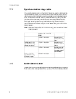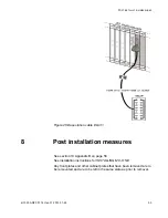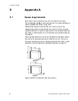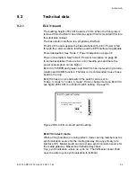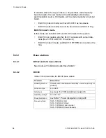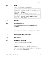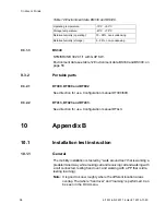
6/1531-ANF 901 14 Uen F1 2013-11-29
51
C
ABLING
7.2 Cable
requirements
All cables used for connecting base stations and for connecting the
synchronization ring must be twisted pair. All cables delivered from
Aastra for connection to the ELU31 board are shielded twisted pair
cables. The shielded pair cables will be connected between the ELU31
and the MDF or MDM or between the first ELU31 board in all magazines
for the synchronization ring. Cables from MDF or MDM to the base
station or another MDF or MDM (for the synchronization ring) must also
be of the twisted pair type.
It is essential that the requirements of the twisted pair cable are main-
tained throughout the entire connection from MDM or MDF to the base
station and also for the synchronization connection. This is particularly
important when using already installed cabling. Other types of cables will
not work and can cause major problems for base station and ring
synchronization communication. The two twisted pairs (SC0, SC1) to the
base station must not be interchanged. For further details see chapter
5.3 Cables between ELU31 board and base stations on page 23.
It is good practise to avoid laying the above mentioned cables close to
other cables carrying high currents and high frequencies. Examples of
cables that should be avoided are power cables for elevators, welding
equipment, heavy machinery and the like. If in doubt whether the envi-
ronment is unsuitable for the ELU31 cabling, use shielded twisted pair
cables. In new installations, it is recommended to use shielded twisted
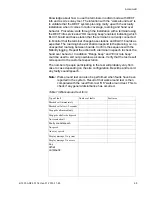
pair cables. All cable data used for base station communication and
synchronization, throughout this document, can be found below, see
table 9 Twisted pair cable data on page 51. Also calculations of power
consumption and cable lengths are based on data below, see chapter
6.2 Dimensioning on page 46.
All pairs used for the synchronization cable must use the same path from
point to point for ACDM to work correctly.
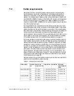
Table 9 Twisted pair cable data
Cable usage
Diameter
mm
Resistance
single wire /km
Capacitance Impedance Maximum
superimposed
noise
Base station/EPP 0.4
137 Ohm
<= 140 nF/km 120 Ohm
10 microV/Hz
0.5
87.5 Ohm
<= 140 nF/km 120 Ohm
10 microV/Hz
0.6
60.7 Ohm
<= 140 nF/km 120 Ohm
10 microV/Hz
Synchronization
0.4
137 Ohm
<= 140 nF/km 120 Ohm
-
0.5
87.5 Ohm
<= 140 nF/km 120 Ohm
-
0.6
60.7 Ohm
<= 140 nF/km 120 Ohm
-

