


Installation and Setup
41-001507-00 REV00 – 04.2014
14
5.
Loosen the screws from the existing telco wall plate enough so that the Wall Mount Base is able to slide in place.
or
Remove the screws from the existing telco wall plate entirely and replace with a set of the provided screws. Ensure
that the screws are loose enough so that the Wall Mount Base is able to slide in place.
Note:
Depending on the wall type, you may need to use wall anchors. Two wall anchors are included with your 6867i IP
Phone
.
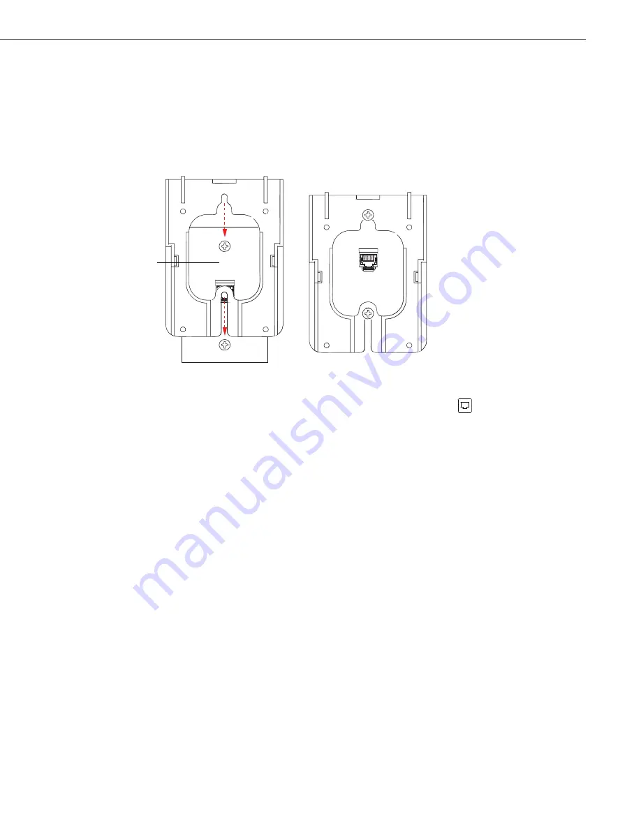
6.
Align the Wall Mount Base above the screw heads (ensuring the Vertical Screw Lock Hole is facing up) on the telco
wall plate and pull down to lock the Wall Mount Base in place.
v
7.
On the back of your phone, connect the provided Ethernet cable into the network port marked with
. Plug the
other end of the Ethernet cable directly into the network jack on the wall.
Wall Mount Base Secured
to Telco Wall Plate
Align and Pull Down
Telco
Wall
Plate


