10 PCM-5894/5892 User Manual
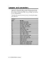
Jumpers and connectors
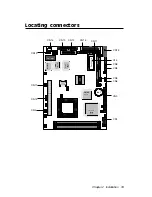
Connectors on the board link it to external devices such as hard
disk drives, a keyboard, or floppy drives. In addition, the board
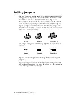
has a number of jumpers that allow you to configure your system
to suit your application.
The table below lists the function of each of the board's jumpers
and connectors.
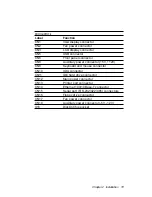
Jumpers
Label
Function
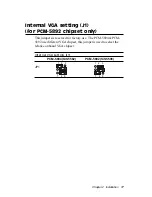
J1
Internal VGA setting
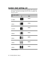
J2
System clock setting
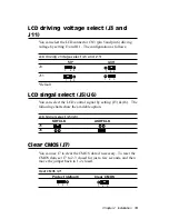
J3
LCD driving voltage select
J5
LCD SHF clock setting
J6
LCD ASHF clock setting
J7
Clear CMOS
J8
CPU frequency ratio
J10
CPU type select
J11
LCD driving voltage select
J12
CPU voltage setting
J13
DOC address select
J14
Ethernet transmitting LED
J15
Ethernet receiving LED
J16
Ethernet link signal LED
J17
COM2 selection
J18
COM2 selection
J19
IRQ selection (COM3, COM4)
J20
COM3 RI Pin voltage select
J21
COM4 RI Pin voltage select
Summary of Contents for PCM-5892
Page 10: ......
Page 18: ...8 PCM 5894 5892 User Manual...
Page 56: ...46 PCM 5894 5892 User Manual...
Page 100: ...9 0 PCM 5894 5892 User Manual...
Page 114: ...104 PCM 5894 5892 User Manual...
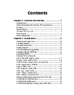
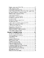
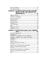
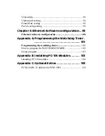
Page 119: ...Appendix C Optional Extras 109 C Optional Extras A P P E N D I X...

