


H a l f - s i z e C P U C a r d
H S B - 8 1 1 P
Appendix A Programming the Watchdog Timer
A-3
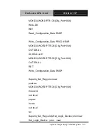
There are three steps to complete the configuration setup: (1) Enter
the MB PnP Mode; (2) Modify the data of configuration registers; (3)
Exit the MB PnP Mode. Undesired result may occur if the MB PnP
Mode is not exited normally.
(1) Enter the MB PnP Mode
To enter the MB PnP Mode, four special I/O write operations are to
be performed during Wait for Key state. To ensure the initial state of
the key-check logic, it is necessary to perform four write opera-tions
to the Special Address port (2EH). Two different enter keys are
provided to select configuration ports (2Eh/2Fh) of the next step.
(2) Modify the Data of the Registers
All configuration registers can be accessed after entering the MB
PnP Mode. Before accessing a selected register, the content of
Index 07h must be changed to the LDN to which the register
belongs, except some Global registers.
(3) Exit the MB PnP Mode
Set bit 1 of the configure control register (Index=02h) to 1 to exit the
MB PnP Mode.
WatchDog Timer Configuration Registers
Summary of Contents for HSB-811P
Page 30: ...Half size CPU Card H S B 8 1 1 P Chapter 3 Award BIOS Setup 3 1 Chapter Award 3 BIOS Setup...
Page 49: ...Half size CPU Card H S B 8 1 1 P Appendix B I O Information B 1 I O Information Appendix B...
Page 50: ...Half size CPU Card H S B 8 1 1 P Appendix B I O Information B 2 B 1 I O Address Map...
Page 51: ...Half size CPU Card H S B 8 1 1 P Appendix B I O Information B 3 B 2 Memory Address Map...
Page 53: ...Half size CPU Card H S B 8 1 1 P Appendix C Mating Connector C 1 Mating Connector Appendix C...