Chapter 3
–
AMI BIOS Setup
71
3.5
” S
ub
co
mp
act
Bo
ard
G
ENE
-E
HL
7
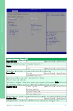
Options Summary: "SMBUS"
SMBUS Slave Address
0
Optimal Default, Failsafe Default
Fill slave address to a SMBUS device, in hexadecimal. Range: 0
–
FF.
Device
is
Is not
Optimal Default, Failsafe Default
Select that robot should or should not do action if condition met.
In condition
Present
Optimal Default, Failsafe Default
Specified register data
Select the condition that robot should check for device.
Present - device is detected.
According to register - Robot read register according to configuration. Note: Device will
be considered 'Present' by Robot, when data read from device is not 0xFF.
Register data is
bitwise equal to
Optimal Default, Failsafe Default
bytewise equal to
bytewise lesser than
bytewise larger than
Select how robot should compare data read from register, to a value configured below.
Register offset
0
Optimal Default, Failsafe Default
Fill register offset (or index) for robot to read, in hexadecimal.\nRange: 0
–
FF.
Summary of Contents for GENE-EHL7
Page 1: ...Last Updated September 26 2023 GENE EHL7 3 5 Subcompact Board User s Manual 1st Ed ...
Page 14: ...3 5 Subcompact Board GENE EHL7 Chapter 1 Chapter 1 Product Specifications ...
Page 18: ...Chapter 1 Product Specifications 5 3 5 Subcompact Board GENE EHL7 1 2 Block Diagram ...
Page 19: ...3 5 Subcompact Board GENE EHL7 Chapter 2 Chapter 2 Hardware Information ...
Page 20: ...Chapter 2 Hardware Information 7 3 5 Subcompact Board GENE EHL7 2 1 Dimensions ...
Page 21: ...Chapter 2 Hardware Information 8 3 5 Subcompact Board GENE EHL7 2 2 Jumpers and Connectors ...
Page 59: ...3 5 Subcompact Board GENE EHL7 Chapter 3 Chapter 3 AMI BIOS Setup ...
Page 62: ...Chapter 3 AMI BIOS Setup 49 3 5 Subcompact Board GENE EHL7 3 3 Setup Submenu Main ...
Page 63: ...Chapter 3 AMI BIOS Setup 50 3 5 Subcompact Board GENE EHL7 3 4 Setup Submenu Advanced ...
Page 65: ...Chapter 3 AMI BIOS Setup 52 3 5 Subcompact Board GENE EHL7 3 4 2 PCH FW Configuration ...
Page 92: ...Chapter 3 AMI BIOS Setup 79 3 5 Subcompact Board GENE EHL7 3 5 Setup Submenu Chipset ...
Page 94: ...Chapter 3 AMI BIOS Setup 81 3 5 Subcompact Board GENE EHL7 3 5 1 1 Memory Configuration ...
Page 97: ...Chapter 3 AMI BIOS Setup 84 3 5 Subcompact Board GENE EHL7 3 5 2 PCI Express Configuration ...
Page 105: ...Chapter 3 AMI BIOS Setup 92 3 5 Subcompact Board GENE EHL7 3 7 1 BBS Priorities ...
Page 107: ...3 5 Subcompact Board GENE EHL7 Chapter 4 Chapter 4 Driver Installation ...
Page 110: ...3 5 Subcompact Board GENE EHL7 Appendix A Appendix A I O Information ...
Page 111: ...Appendix A I O Information 98 3 5 Subcompact Board GENE EHL7 A 1 I O Address Map ...
Page 112: ...Appendix A I O Information 99 3 5 Subcompact Board GENE EHL7 ...
Page 113: ...Appendix A I O Information 100 3 5 Subcompact Board GENE EHL7 A 2 Memory Address Map ...
Page 114: ...Appendix A I O Information 101 3 5 Subcompact Board GENE EHL7 ...
Page 115: ...Appendix A I O Information 102 3 5 Subcompact Board GENE EHL7 A 3 IRQ Mapping Chart ...
Page 116: ...Appendix A I O Information 103 3 5 Subcompact Board GENE EHL7 ...
Page 117: ...Appendix A I O Information 104 3 5 Subcompact Board GENE EHL7 ...
Page 118: ...3 5 Subcompact Board GENE EHL7 Appendix B Appendix B Mating Connectors and Cables ...


