Chapter 3
–
AMI BIOS Setup
58
3.5
” S
ub
co
mp
act
Bo
ard
G
ENE
-E
HL
7
3.4.5.1
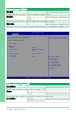
Smart Fan Mode Configuration
Options Summary
FAN1 Output Mode
Output PWM mode
(open drain)
Linear Fan Application
Output PWM mode
(push pull)
Optimal Default, Failsafe Default
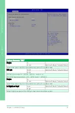
Fan 1 Smart Fan Control
Manual Duty Mode
Auto Duty-Cycle Mode Optimal Default, Failsafe Default
Smart Fan Mode Select.
Temperature Source
CPU(PECI) Temperature
System Temperature
Optimal Default, Failsafe Default
System Temperature 2
Select the monitored temperature source for this fan.
Temperature 1
60
Duty Cycle 1
85
Summary of Contents for GENE-EHL7
Page 1: ...Last Updated September 26 2023 GENE EHL7 3 5 Subcompact Board User s Manual 1st Ed ...
Page 14: ...3 5 Subcompact Board GENE EHL7 Chapter 1 Chapter 1 Product Specifications ...
Page 18: ...Chapter 1 Product Specifications 5 3 5 Subcompact Board GENE EHL7 1 2 Block Diagram ...
Page 19: ...3 5 Subcompact Board GENE EHL7 Chapter 2 Chapter 2 Hardware Information ...
Page 20: ...Chapter 2 Hardware Information 7 3 5 Subcompact Board GENE EHL7 2 1 Dimensions ...
Page 21: ...Chapter 2 Hardware Information 8 3 5 Subcompact Board GENE EHL7 2 2 Jumpers and Connectors ...
Page 59: ...3 5 Subcompact Board GENE EHL7 Chapter 3 Chapter 3 AMI BIOS Setup ...
Page 62: ...Chapter 3 AMI BIOS Setup 49 3 5 Subcompact Board GENE EHL7 3 3 Setup Submenu Main ...
Page 63: ...Chapter 3 AMI BIOS Setup 50 3 5 Subcompact Board GENE EHL7 3 4 Setup Submenu Advanced ...
Page 65: ...Chapter 3 AMI BIOS Setup 52 3 5 Subcompact Board GENE EHL7 3 4 2 PCH FW Configuration ...
Page 92: ...Chapter 3 AMI BIOS Setup 79 3 5 Subcompact Board GENE EHL7 3 5 Setup Submenu Chipset ...
Page 94: ...Chapter 3 AMI BIOS Setup 81 3 5 Subcompact Board GENE EHL7 3 5 1 1 Memory Configuration ...
Page 97: ...Chapter 3 AMI BIOS Setup 84 3 5 Subcompact Board GENE EHL7 3 5 2 PCI Express Configuration ...
Page 105: ...Chapter 3 AMI BIOS Setup 92 3 5 Subcompact Board GENE EHL7 3 7 1 BBS Priorities ...
Page 107: ...3 5 Subcompact Board GENE EHL7 Chapter 4 Chapter 4 Driver Installation ...
Page 110: ...3 5 Subcompact Board GENE EHL7 Appendix A Appendix A I O Information ...
Page 111: ...Appendix A I O Information 98 3 5 Subcompact Board GENE EHL7 A 1 I O Address Map ...
Page 112: ...Appendix A I O Information 99 3 5 Subcompact Board GENE EHL7 ...
Page 113: ...Appendix A I O Information 100 3 5 Subcompact Board GENE EHL7 A 2 Memory Address Map ...
Page 114: ...Appendix A I O Information 101 3 5 Subcompact Board GENE EHL7 ...
Page 115: ...Appendix A I O Information 102 3 5 Subcompact Board GENE EHL7 A 3 IRQ Mapping Chart ...
Page 116: ...Appendix A I O Information 103 3 5 Subcompact Board GENE EHL7 ...
Page 117: ...Appendix A I O Information 104 3 5 Subcompact Board GENE EHL7 ...
Page 118: ...3 5 Subcompact Board GENE EHL7 Appendix B Appendix B Mating Connectors and Cables ...


