


USER’S MANUAL
◆
Screw the joint of the high-pressure hose and fix it on
the base.
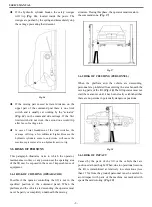
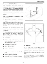
4.4.2 HYDRAULIC PALNT
◆
Install the pump on the hock board according to
Fig.
32
and fix it on the bottom of main column.
Fig. 32
◆
Connect the hydraulic unit to the circuit crossing with
◆
Tight all the fittings very well, even the one already
mounted by the manufacturer.
◆
Fill the hydraulic unit tank with 8 liters of hydraulic
oil ISO 32 as IP HYDRUS OIL 32, SHELL TELLUS
OIL T32 or similar
(See Chapter 2, TECHNICAL
SPECIFICATIONS)
.
◆
Remove the oil filling cap and substitute it with the
given drain cap.
4.4.3 ELECTRIC PLANT CONNECTION
WARNING
The operations listed below must be performed by skilled
personnel.
4.4.3.1
Before connecting the electric system, make sure
that:
◆
The power supply plant to the lift is equipped with the
protection device required by current standards in the
country where the machinery is installed.
◆
The power supply line has the following cross-section:
Lift voltage 400V, three-phase………….……Min. 2.5mm
2
Lift voltage 230V, three-phase…………………Min. 4mm
2
Lift voltage 230V, single-phase……………..…Min. 6mm
2
◆
The voltage oscillations are within the tolerance range
set forth by the specifications.
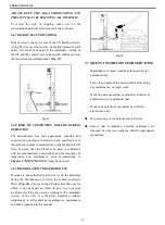
The manufacturer supplies the rack to operate at 400V with
a three-phase configuration; if the line voltage is different,
the motor and transformer connection must be changed.
(Fig. 33)
It is also necessary to replace the thermal relay
requesting that part from the manufacture and/or service
center.
Motor
Trasformer
W2 U2 V2 W2 U2 V2
U1 V1 W1 U1 V1 W1
L1 L2 L3 L1 L2 L3
0
0 24
Fig. 34
4.4.3.2
Connect the power supply cable and end limit
switch wire to the terminal strip on the junction box of the
motor
(Fig. 35)
following the wiring diagram on
Page 4.
-
13
-
Summary of Contents for AA-2PFP45
Page 26: ...USER S MANUAL 23 ...
Page 27: ...USER S MANUAL 24 ...


