4
Pump Motors
A.O.Smith
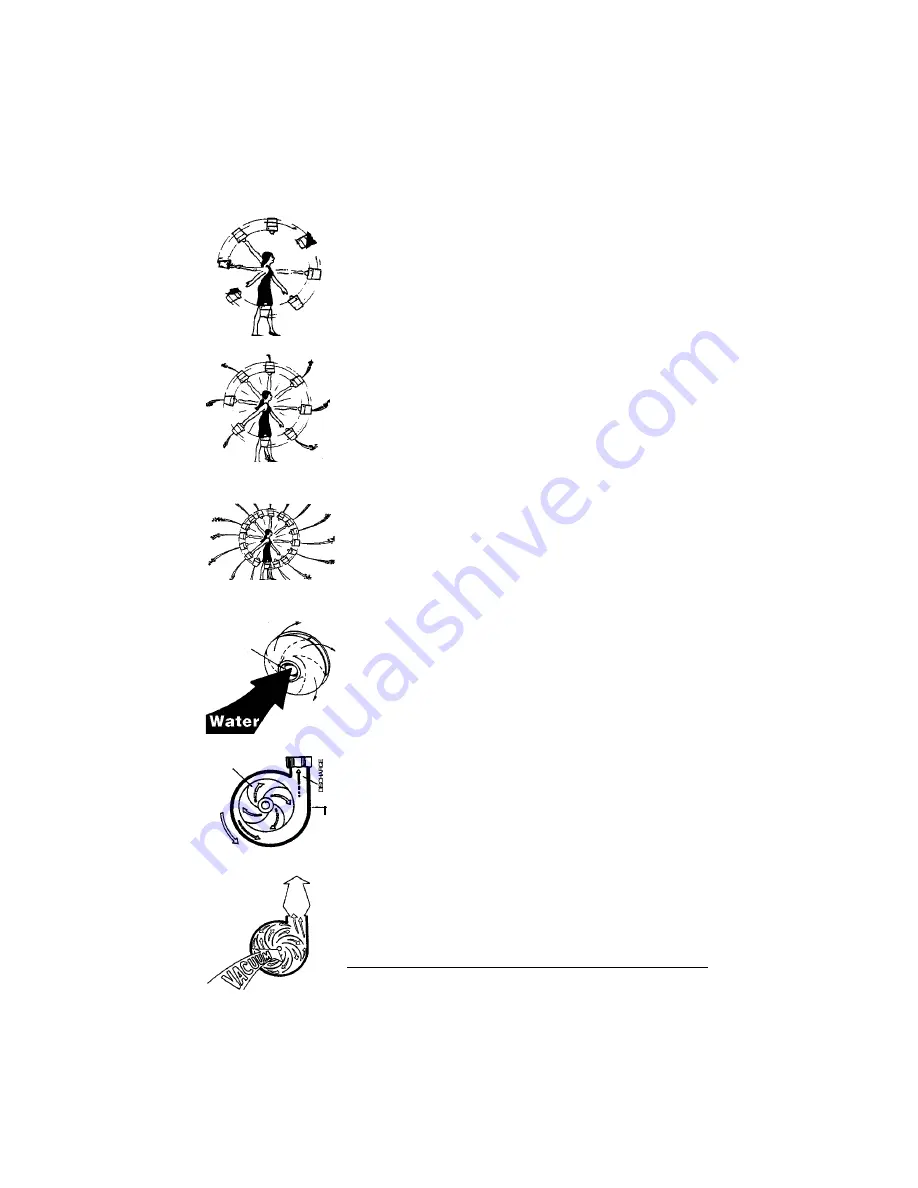
The principle of operation can be demonstrated
by a whirling bucket of water. As the bucket is
rotated (figure 1), the water is held in the bucket
by centrifugal force. If we were to punch a hole
in the bottom of the bucket, the water would be
forced out, again by centrifugal force (figure 2).
Speeding up the rotation of the bucket, the water
would exit with greater force (figure 3).
This same principle is performed by the
impeller of the pump. As the motor turns the
impeller, the water is forced through the impeller
vanes toward the outside edge (figure 4). The
spinning action of these vanes generates cen-
trigual force (figure 5). This action imparts
kinetic or velocity energy into the water. As the
water is propelled to the outer edge of the
impeller, there is a reduction in pressure at the
eye of the impeller, creating a “vacuum” (figure
6).
The combination of atmospheric pressure on
the surface of the water and vacuum at the eye of
the impeller, causes the water to flow in the “suc-
tion pipe” to the pump.
The amount of pressure imparted into the
water by the impeller is determined in part by
the size and design of the impeller which also
effects forces placed on the motor. There are
basically two types of impellers used on these
applications; the semi-open has vanes exposed on
the front or receiving side. The back side is
closed by a shroud (figure 7). A closed impeller is
designed to have two shrouds completely enclos-
ing the vane area of the impeller (figure 8).
IMPELLER
ROTATION OF
IMPELLER
FLOW
UNDER
PRESSURE
VOLUTE
5
6


