34
INTERNAL CONTAMINANTS
The system must be internally cleaned and flushed after a new or
replacement unit has been installed to remove contaminants that
may have accumulated during installation. This is doubly important
when a replacement unit is installed into an existing system where
Stop Leak or other boiler additives have been used.
All systems should be completely flushed with a grease removing
solution to assure trouble-free operation. Pipe joint compounds,
soldering paste, grease on tubing and pipe all tend to contaminate
a system.
Failure to clean and flush the system can cause solids to form on
the inside of the heat exchanger, can produce acid concentrations
that become corrosive, can allow excessive amounts of air or other
gases to form which could block circulation, foul system
accessories and damage circulator seals and impellers.
It is recommended that after installation, the boiler and system
when filled should include the proper percentage of cleaning
solution related to approximate water volume of the system. Fire
and circulate for about one hour and then flush clean with fresh
water. Commercial grease removing solutions are available.
PRECAUTIONS
If the unit is exposed to the following, do not operate boiler until all
corrective steps have been made by a qualified serviceman:
1. Exposure to fire.
2. If damaged.
3. Firing without water.
4. Sooting.
If the heater has been exposed to flooding it must be replaced.
IMPORTANT
ONLY QUALIFIED PERSONNEL SHALL PERFORM THE INITIAL
FIRING OF THE HEATER. AT THIS TIME THE USER SHOULD
NOT HESITATE TO ASK THE INSTALLER ANY QUESTIONS
REGARDING THE OPERATION AND MAINTENANCE OF THE UNIT.
CHECKING AND ADJUSTING THE INPUT
NOTE: For high altitude installations, calculate the input rate in
accordance with the procedure in the HIGH ALTITUDE
INSTALLATIONS in the OPERATING INSTRUCTIONS section.
1. Attach a pressure gauge or a manometer to the gauge port.
Check for correct manifold pressure. PRESSURE SHOULD
NOT EXCEED VALUE INDICATED ON RATING PLATE.
2. Use this formula to “clock” the meter. Be sure that other gas
consuming appliances are not ON during this interval.
3600
x H = Btuh
T
T = Time in seconds to burn one cubic foot of gas.
H = Gas heating value (Btu per cubic foot of gas).
Btuh = Actual boiler input per hour.
IMPORTANT
UNDER NO CIRCUMSTANCES SHALL THE GAS PRESSURE
MEASURED AT THE BURNER MANIFOLD EXCEED THAT
STATED ON THE BOILER RATING PLATE. OVERFIRING WILL
RESULT IN DAMAGE TO THE BOILER, AS WELL AS INCREASED
RISK OF FIRE, SOOTING AND ASPHYXIATION.
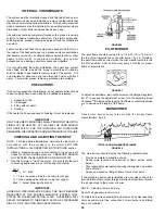
FIGURE 26
PILOT BURNER
The pilot flame should envelop 3/8 to 1/2 inch (10 to 12 mm) of
the top of the insulated rod on the pilot burner, fig. 26. Normally,
the pilot flame will be correct when the pilot manual valve is in the
full “ON” position. Check pilot burner every 3 months for proper
flame characteristics.
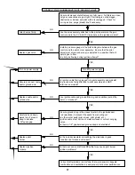
FIGURE 27
To adjust the pilot flame, remove the screw on the pilot gas regulator,
fig. 27, to expose the adjustment screw. Turn the adjusting screw
clockwise
to increase the length of the flame or counterclockwise
to decrease the length of the flame.
MAIN BURNER
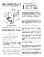
Check main burner every three months for proper flame
characteristics, fig. 28.
TYPICAL AND MAIN BURNER FLAMES
FIGURE 28
The main burner should display the following characteristics:
•
Provide complete combustion of gas.
•
Cause rapid ignition and carryover of flame across entire
burner.
•
Give reasonably quiet operation during initial ignition, operation
and extinction.
•
Cause no excessive lifting of flame from burner ports.
If the preceding burner characteristics are not evident, check for
accumulation of lint or other foreign material that restricts or blocks
the air openings to the burner or boiler.
NOTE: Cleaning of main burners.
Shut off all gas and electric to unit.
Complete burner tray assembly may be removed by disconnecting
union assembly, pilot line connection at main burner and sliding
tray out of cabinet.

