


7
THERMAL BALANCER
Figure 4 shows the internal wiring of the thermal balancer. The
device may be tested after disconnecting the four leads from
their respective terminals on the unit.
1.
Apply a test light to the yellow and red leads.
• The lamp should light as the contact in this circuit is
normally closed when the resistor is cool.
2.
Apply a light to the black and yellow leads.
• The lamp should not light as the contact in this circuit is
normally open when the resistor is cool.
3.
Remove the test light.
4.
Apply 120 volts to the white and red leads which power the
1900 ohm resistor. After a warming period the contacts of
the thermal balancer should operate.
5.
Remove the test light.
6.
Apply the test light as described in steps 1 and 2.
While the resistor is still warm the lamp indications should be the
opposite as described previously.
MANUAL RESET HIGH LIMIT
This boiler is equipped with a manual reset high limit switch,
located under the small cover on the side of the jacket, see
Figure 5. This device provides positive shutdown of the boiler
in the event of boiler or system malfunction. Should the surface
temperature of the copper tubing heat exchanger reach 250°F
(120°C), the high limit switch will activate, the gas control valve
will close, the pilot and main burners will be extinguished. If
the high limit switch should shut off unit, check the following
conditions:
• No water in boiler.
• Restricted water flow through the boiler.
• Improper wiring (boiler firing without circulating pump
operating).
• Pump failure.
After correcting failure condition remove the protector switch
cover and push the reset button. The high limit switch may be
reset after the coil surface cools to 6°F (3.3°C) below the trip
setting.
AUTO RESET HIGH LIMIT
The high limit is a safety device wired in series with the ignition
system. Set the high limit control to approximately 100°F above
the maximum designed system temperature. If the boiler outlet
water temperature should exceed the high limit setting, the main
gas control valve will close but the circulating pump will continue
to operate. Maximum adjustable setting is 115°C (239°F) cut-out
with a 30°C (86°F) to 250°C (482°F) adjustable differential, see
Figure 2.
INTERMITTENT IGNITION CONTROL MODULE
The Honeywell S-8600 control module contains the electronic
components of the system and also serves as a control wiring
system for the controls mounted on the boiler. The control
module performs the following functions:
1.
Checks for safe-start by sensing for a false flame condition
on start-up.
2.
Generates a potential of 15,000 volts for spark ignition of the
pilot burner.
3.
Opens the pilot valve.
4.
Discontinues ignition spark when the pilot flame is
established. The S-8600 control used on propane
gas models provides safety lockout if the pilot
fails to ignite within the pilot flame establishing
period. The S-8600 control used on natural gas
models continues trial for ignition until pilot flame
is established.
5.
After proof of pilot flame, opens then main valve.
6.
On a power loss, shuts the boiler down. When power is
restored it will begin a new ignition cycle.
7.
On a loss of flame, shuts off main gas and starts trial for pilot
ignition.
Please refer to Troubleshooting section for more information.
FIGURE 2. AUTO RESET HIGH LIMIT
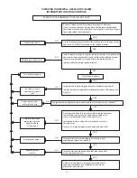
FIGURE 3. S-8600 INTERMITTENT IGNITION CONTROL
MODULE (IID)
FIGURE 4. THERMAL BALANCER
FIGURE 5. HIGH LIMIT SWITCH
Summary of Contents for Burkay HW-300
Page 4: ...4 GENERAL SAFETY...
Page 6: ...6 Figure 1 COMPONENT LOCATIONS CONTROL COMPONENTS...
Page 14: ...14 LIGHTING AND OPERATING INSTRUCTIONS NATURAL AND PROPANE FOR HW300 HW399...
Page 15: ...15 LIGHTING AND OPERATING INSTRUCTIONS NATURAL AND PROPANE WITH I I D FOR HW420 UP...
Page 26: ...26 NOTES...