A.O. Smith Burkay HW-300 User Manual Download Page 18

18

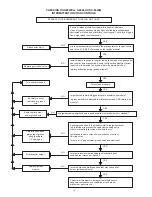
CHECKING HONEYWELL S-8600H OR S-8600M 

INTERMITTENT IGNITION CONTROLS 

SPARK AT PILOT BURNER BUT PILOT WILL NOT LIGHT

Ensure all manual shutoff valves are fully open; all filters are 


clean; all gas connections are gas tight; pilot tubing is not damaged, 

obstructed or kinked; and pilot orifice is unclogged. Check for air in gas 

line, purge (bleed) line if necessary. 

Are the wires securely attached to the pilot operator on the gas control 

and to the PV & MV/PV terminals on the ignition module? 

Install a pressure gauge in the pilot tubing line between the gas control 

and the pilot burner assembly. Ensure that the pilot adjustment screw 

(under cap) is adjusted to a position that will permit gas to flow.

Is pilot gas flowing during ignition attempt?

Turn off power supply.

Is ignition cable firmly plugged into pilot assembly and module?  

Is ground wire firmly attached to pilot assembly and GND terminal on 

module?

Are ignition cable and ground wire in good condition (not brittle, burnt, or cracked)?

Ensure ground strap is the closest metal to the igniter/sensor 

rod (electrode) to prevent the spark from shorting out to 

other metal parts (pilot screen, pilot shield, etc.).

Ignition cable must not touch metal surfaces or current 

carrying wires.

Is there a 1/8” gap between ground strap and electrode?

Is ceramic insulator surrounding the electrode in good 

condition (not cracked or broken)?

Is there excessive draft conditions that may cause pilot 

burner ignition problems?

Correct draft problems in a manner that would ensure 

adequate combustion and ventilation air and proper 

pilot burner performance.

YES

YES

YES

YES

YES

YES

YES

NO

NO

NO

NO

NO

NO

NO

Attach wires firmly.

Replace gas control valve.

Turn on power supply.

Securely connect 

cable and/or ground 

wire.

Replace pilot burner

 and/or ground wire.

Carefully bend down-

wards top of ground

strap to achieve

1/8” spark gap.

Replace pilot burner.

Replace ignition

module.

YES

YES

Summary of Contents for Burkay HW-300

Page 1: ...exactly a fire or explosion may result causing property damage personal injury or death Do not store or use gasoline or other flammable vapors and liquids in the vicinity of this or any other applian...

Page 2: ...OMPONENTS 6 BOILER START UP AND OPERATIONS 10 Filling the system 10 Precautions 10 Pilot and main burner 10 Checking and adjusting input 12 TROUBLESHOOTING 16 MAINTENANCE PROCEDURES 24 Manual reset hi...

Page 3: ...y hazardous situation which if not avoided could result in property damage WARNING CAUTION CAUTION DANGER All safety messages will generally tell you about the type of hazard what can happen if you do...

Page 4: ...4 GENERAL SAFETY...

Page 5: ...l Code CSA C22 1 ABBREVIATIONS USED Abbreviations found in this Instruction Manual include ANSI American National Standards Institute ASME American Society of Mechanical Engineers NEC National Electri...

Page 6: ...6 Figure 1 COMPONENT LOCATIONS CONTROL COMPONENTS...

Page 7: ...push the reset button The high limit switch may be reset after the coil surface cools to 6 F 3 3 C below the trip setting AUTO RESET HIGH LIMIT The high limit is a safety device wired in series with t...

Page 8: ...h ASME code Properly sized Pressure Relief Valve must be installed in opening provided Can result in overheating and excessive tank pressure Can cause serious injury or death Water Damage Hazard Press...

Page 9: ...lower water temperatures be used to avoid the risk of scalding It is further recommended in all cases that the water temperature be set for the lowest temperature which satisfies the user s hot water...

Page 10: ...iators or convectors PRECAUTIONS If the unit is exposed to the following do not operate boiler until all corrective steps have been made by a qualified service technician Flooding to level of burner o...

Page 11: ...ee Figure 7 Check for good terminal connection at the sensing probe at the pilot burner assembly if pilot does not light Check for electrical power to the valve If electrical power and gas are present...

Page 12: ...this formula to clock the meter Be sure that other gas consuming appliances are not ON during this interval 3600 x H Btuh T Btuh The approximate actual input rate T Time in seconds to burn one cubic f...

Page 13: ...M After 15 sec ignition shut down 5 minute time delay before re try S 8600H After 15 sec ignition system locks out must be manually reset FLAME CURRENT SENSED Spark generator off Second valve operator...

Page 14: ...14 LIGHTING AND OPERATING INSTRUCTIONS NATURAL AND PROPANE FOR HW300 HW399...

Page 15: ...15 LIGHTING AND OPERATING INSTRUCTIONS NATURAL AND PROPANE WITH I I D FOR HW420 UP...

Page 16: ...ff delay of approximately 2 minutes Pump and burner remain on Tank temperature control thermostat defective Replace System wiring is incorrect Correct wiring Circulating pump on Pump wired for continu...

Page 17: ...ceramic insulator surrounding the electrode cracked or broken Replace pilot burner assembly Replace ignition module Turn on gas supply Turn on power supply Securely connect cable and or ground wire Ca...

Page 18: ...ttached to pilot assembly and GND terminal on module Are ignition cable and ground wire in good condition not brittle burnt or cracked Ensure ground strap is the closest metal to the igniter sensor ro...

Page 19: ...sensor rod in good condition not broken or cracked Is the igniter sensor rod in good condition not worn corroded sooted or damaged Replace ignition module Correct the situation by consulting the inst...

Page 20: ...lot ground wire firmly attached to the pilot assembly and GND terminal on module Are high voltage cable and ground wire in good condition not brittle burnt or cracked Make sure pilot flame spreader ho...

Page 21: ...below minimum threshold for system operation not applicable A Flash Code Descriptions Heartbeat Constant 1 2 second bright 1 2 second dim cycles The flash code number signifies that the LED flashes X...

Page 22: ...ontrol remains in wait mode When the fault corrects control resumes normal operation after a one minute delay Check transformer and AC line for proper input voltage to the control Check with full syst...

Page 23: ...r proper input voltage to the control Check with full system load on the transformer 6 2 Failed trial for ignition resulting in lockout Remain in lockout until Call for Heat is cycled Check gas supply...

Page 24: ...r bad leads With leads attached depress the switch button If the meter does not read zero the switch is defective and must be replaced PRESSURE RELIEF VALVE TEST Burn hazard Hot water discharge Keep c...

Page 25: ...w boiler parts and vent to cool before disassembly 2 Remove the boiler draft diverter and vent pipe running to the chimney Check parts and chimney for obstructions and clean as necessary 3 Remove burn...

Page 26: ...26 NOTES...

Page 27: ...te or provincial law are limited to one 1 year dura tion for the boiler or any of its parts Some states and provinces do not allow limitations on how long an implied warranty lasts so the above limita...

Page 28: ...28 25589 Highway 1 McBee SC 29101 Technical Support 800 527 1953 Parts 800 433 2545 Fax 800 644 9306 www hotwater com...

Reviews: