


24
MAINTENANCE PROCEDURES
These boilers are designed to give many years of efficient and
satisfactory service when properly operated and maintained.
To assure continued good performance, the following
recommendations are made.
The area around the boiler should be kept clean and free from
lint and debris. Sweeping the floor around the boiler should be
done carefully. This will reduce the dust and dirt which may enter
the burner and pilot air passages, causing improper combustion
and sooting.
The flow of combustion and ventilation air to the boiler must not
be obstructed. The boiler area must be kept clear and free from
combustible materials, gasoline, and other flammable vapors
and liquids.
Any safety devices including low water cutoffs used in conjunction
with this boiler should receive periodic (every six months)
inspection to assure proper operation. A low water cutoff device
of the float type should be flushed every six months. All pressure
relief valves should be inspected and manually operated at
least twice a year. More frequent inspections may be necessary
depending on water conditions.
Periodic checks, at least twice a year, should be made for water
and/or gas leaks.
The boiler mounted gas and electrical controls have been
designed to give both dependable service and long life.
However, malfunction can occur, as with any piece of equipment.
It is therefore recommended that all components be checked
periodically by a qualified service technician for proper operation.
MANUAL RESET HIGH LIMIT SWITCH CONTINUITY
TEST
Do not depress the switch reset button prior to testing. With the
boiler being cold, disconnect the leads from the switch. With a
multimeter place a probe on each side of the switch. If the meter
reads zero the switch is good. If you receive an infinite or OL
signal, the reason could be:
1.
Switch contacts open.
• Depress reset button on switch (switch cannot be reset
until water temperature in the boiler coils drop below
200°F). Meter should read zero.
2.
Defective switch or bad leads.
• With leads attached, depress the switch button. If the
meter does not read zero, the switch is defective and
must be replaced.
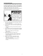
PRESSURE RELIEF VALVE TEST
Burn hazard.
Hot water discharge.
Keep clear of Pressure
Relief Valve discharge outlet.
If after manually operating the valve, it fails to completely reset
and continues to release water, turn off power to the boiler at
the main disconnect switch or breaker. Close the cold water inlet
to the boiler and follow the draining instructions in this manual
to drain the boiler. Should the pressure relief valve need to be
replaced, call the toll free phone number listed on the back of this
manual for further technical assistance.
CLEANING AND FLUSHING INSTRUCTIONS
INTERNAL CONTAMINANTS
The hydronic system must be internally cleaned and flushed
after a new or replacement boiler has been installed to remove
contaminants that may have accumulated during installation.
This is doubly important when a replacement boiler is installed
into an existing system where stop leak or other boiler additives
have been used.
Failure to clean and flush the system can produce acid
concentrations that become corrosive, cause gases to form
that block water circulation or lead to formation of deposits on
the boiler surfaces, any of which could result in damage to the
system and circulating pump.
All hot water heating systems should be completely flushed with
a grease removing solution to assure trouble-tree operation.
Pipe joint compounds, soldering paste, grease on tubing and
pipe all tend to contaminate a system.
Failure to flush contaminates from a system can cause solids to
form on the inside of boiler heat exchangers, create excessive
amounts of air and other gases to block circulation, foul various
system accessories and even deteriorate circulation seals and
impellers.
It is recommended that after installation, the boiler and system
when filled should include the proper percentage of cleaning
solution related to approximate water volume of the system. Fire
and circulate for about one hour and then flush clean with fresh
water. Commercial grease removing solutions are available from
your distributor.
FIGURE 10. PRESSURE RELIEF VALVE TEST
Summary of Contents for Burkay HW-300
Page 4: ...4 GENERAL SAFETY...
Page 6: ...6 Figure 1 COMPONENT LOCATIONS CONTROL COMPONENTS...
Page 14: ...14 LIGHTING AND OPERATING INSTRUCTIONS NATURAL AND PROPANE FOR HW300 HW399...
Page 15: ...15 LIGHTING AND OPERATING INSTRUCTIONS NATURAL AND PROPANE WITH I I D FOR HW420 UP...
Page 26: ...26 NOTES...