background image

A. O. Smith Water Products Company

       Service Handbook

Irving, Texas 2000©


Training Department

12

VENTING

Equivalent Feet of Pipe Intake or Exhaust

MANIFOLD GAS


SUPPLY GAS

Gas Type

Minimum 

Inches 

W.C.

Maximum 

Inches 

W.C.

Natural

5

10.5

Propane

11

13.8

NOTE: Pressure without capacity will result in
lockout. Follow the piping guidelines in the
instruction manual.
The supply gas pressure in normally measured
at the dirt leg or at the inlet gas pressure tapping
on the gas valve. This reading must be measured
with 'flowing' gas.

Regulated Gas Supply
Line

Main Gas Shutoff Valve

Dirt Leg Tee

The manifold gas pressure is measured at the
manifold pressure tap of the gas valve when the
gas is flowing.

The gas valves used on all BTH water heaters are
24 volt AC combination step opening gas valves.
They incorporate the main valve, and gas pressure
regulators into one body.

Pipe Cap

Pressure Regulator Adjustment
(Cover Screw)

Inlet Pressure Tap

Gas Inlet

Gas Valve On/Off

TH & TR Terminals
(Main Valve)

Manifold
Pressure Tap

Gas Outlet

Gas Type

Minimum/Maximum 
Inches W.C.150/199

Minimum/Maximum 

Inches W.C. 120/250

Natural

3.5

4.0

Propane

10

10.0

Number of 

90° Elbows

3" Minimum 

Pipe (Feet)

3" 

Maximum 

Pipe (Feet)

4" 

Maximum 

Pipe 

(Feet)

One (1)

7

45

115

Two (2)

7

40

110

Three (3)

7

35

105

Four (4)

7

30

100

Five (5)

7

95

Six (6)

7

90

VENT LENGTH TABLE

4-inch PVC may be used for a MAXIMUM intake of ONE HUNDRED TWENTY (120) EQUIVALENT FEET
and a MAXIMUM exhaust of ONE HUNDRED TWENTY (120) EQUIVALENT FEET.  The maximum number
of 90° elbows with the 4-inch venting is six (6) on the intake and six (6) on the exhaust.  A 90° elbow is equal
to five (5) equivalent feet of pipe.  One (1) 90° elbow is equal to two (2) 45° elbows.  Any venting configuration
using less than 50 equivalent feet should use 3-inch venting.  See Vent Length Table.

The 3-inch venting terminals (provided) must be used with the 4-inch venting by adding 4 x 3 reducing
couplings at the venting terminals.  A reducing coupling is also needed immediately after the condensate
elbow (exhaust) and immediately before the 3-inch blower adapter (intake) if direct venting is installed.  See
Vent Length Table.

--
--

Summary of Contents for BTH 120

Page 1: ...tNo TC 044R2 15 00 Printed in the U S A 3 00 This Service Handbook was prepared by The Training Department Irving Texas BTH 120 150 199 250 Service Handbook Includes Parts List For Series 960 through...

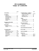
Page 2: ...Troubleshooting Pre Service 18 Igniter Continuity Check 18 19 Control Board Check 20 Transformer 21 22 Control Board 22 23 Temperature 24 Blower 25 26 PAGE Troubleshooting continued Pressure Switch C...

Page 3: ...rther assistance This handbook is intended for use by licensed plumbing professionals and reference should be made to the instruction manual accompanying the product This handbook contains supplementa...

Page 4: ...es from the sides and rear 0 inches from vent piping and 1 5 inches from the top cover A 24 inch clearance for all serviceable parts is recommended Clearances may vary between BTH models See instructi...

Page 5: ...Within 10 4 Minimum 4 Minimum 4 Minimum Exhaust 3 Minimum From Inside Corner Recommended Vent Hood Must Be Mounted 4 Minimum Below Doors and Windows Vent Hood Must Be Mounted 4 Minimum Below Windows...

Page 6: ...s to natural and propane gas models The National Fuel Code also specifies minimum make up air opening sizes for various building installations Ref NFPA 54 ANSI Z223 1 sec 5 3 MAKE UP AIR DIRECT VENT I...

Page 7: ...elief opening for flue gases should the vent become obstructed or a down draft condition occur Additionally when the heater is installed in a confined space and communicating with the outdoor air one...

Page 8: ...al to install vertical make up air ducts to the out doors Again two openings are required within 12 inches 30 cm of the top of the enclosure and one within 12 inches 30 cm of the bottom of the enclosu...

Page 9: ...ts should be installed When using horizontal ducts two openings are required within 12 inches 30 cm of the top of the enclosure and one within 12 inches 30 cm of the bottom of the enclo sure Each open...

Page 10: ...p air requirements This may result in air being backdrafted by the restaurant exhaust equipment through the heater causing flue gas spill age flame roll out improper combustion inconsistent pilot oper...

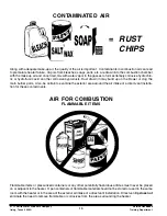
Page 11: ...byproducts Dust drawn in may build up on the blower or clog the main burner ports Also be certain to examine the exterior area around the air intake of a direct vent installa tion for these contamina...

Page 12: ...pH 5 is 10x10 100 times pH 7 and pH 4 is 10x10x10 1 000 times pH 7 etc WHAT ABOUT CONDENSATE NEUTRALIZERS Condensate neutralizers are usually not necessary A condensate neutralizer is easy to make by...

Page 13: ...Off TH TR Terminals Main Valve Manifold Pressure Tap Gas Outlet Gas Type Minimum Maximum Inches W C 150 199 Minimum Maximum Inches W C 120 250 Natural 3 5 4 0 Propane 10 10 0 Number of 90 Elbows 3 Mi...

Page 14: ...ve Press BTH 120 and 250 Only Low Supply Gas Pressure Switch NC 4 3 w c gas press to close If ECO is closed low gas pressure switch is closed 120 250 models only Blocked Outlet NC Opens at 2 5 Positiv...

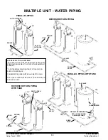
Page 15: ...ATION HOSE MUST BE ALLOWED TO DRAIN NOTE T P VALVES MUST BE PIPED TO OPEN DRAIN OR PER LOCAL CODE MULTIPLE UNIT WATER PIPING REVERSE RETURN PIPING WITH TANK 2 HOT TO FIXTURES VENT TO OUTDOORS 2 T P EX...

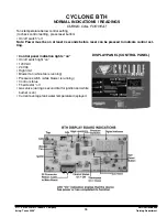
Page 16: ...f switch on Note Power must be on at least 4 seconds before reset can be pressed to indicate control set ting Control panel indication lights on On off switch light on 120 VAC 24 VAC High limit Blower...

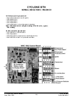
Page 17: ...1 CN 2 black term 1 CN 4 black term 1 CN 5 white term 1 only while ignitor is heating Note CN 6 black term 2 will give reading of 90 100 volts ignore this reading 24 VAC present to ground and CN 3 red...

Page 18: ...black term 1 Note CN 6 black term 2 flame sensor may display 90 100 VAC this is a non reading ignore it 24 VAC present to ground and CN 3 red term 1 and red term 4 CN 4 blue term 4 CN 6 brown term 4 B...

Page 19: ...ull of water Exhaust and intake vent do not exceed allowable limits All plugs into boards are secure Condensate hose is drained and open 115 120 VAC is supplied to the heater including polarity check...

Page 20: ...Continuity Through The Valve Coil Power off Gas valve coil continuity check Disconnect wires from gas valve Multimeter set to scale IF meter does not indicate 7 5 of table meter indicates 7 5 of table...

Page 21: ...ONTROL BOARD CN1 CONNECTION Disconnect plug from CN1 terminal Power switch On 120 VAC indicator light should be On Check for 120 VAC black wire terminal to white wire terminal on plug IF 120 V A C is...

Page 22: ...FORMER TEST STEP 4 120 VAC SUPPLIED TO 24 VAC TRANSFORMER CN4 Disconnect CN 4 plug from board Check for 120 VAC between the black terminal connect and white terminal connect on the control board IF TH...

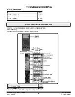
Page 23: ...ECO wires STEP 6 CONTROL BOARD TEST STEP 5 24 VAC FROM TRANSFORMER STEP 5 24 VAC FROM TRANSFORMER 24 VAC transformer indicator light should be on Insert probe into back of connect Check for 24 VAC blu...

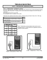
Page 24: ...MISTOR Reinstalled plug Check for 24 VAC from back of red 1 plug to ground IF THE N 24 V AC is not present replace 24 V AC is present go to st Note Resistance thru E CO plug red 1 to plug red 4 is 5 o...

Page 25: ...ltimeter to read resistance 20 K scale Check the ohm s resistance from black to black on the CN 3 plug and black to black on the CN 8 plug IF THEN Ohm reading does not approximately correspond to tabl...

Page 26: ...to gnd does show 120 VAC blower is running blower is not runn Reconnect plugs to board Blower operation check Tank must be calling for heat minimum setting available is 80 F Set multimeter to read 120...

Page 27: ...d plug into the control board recepticles CN 2 CN 5 and CN 6 120 VAC present at CN 2 term 1 to gnd Blower not running Tank is calling for heat STEP 9A Check for 120 VAC from blower speed reduction boa...

Page 28: ...itch does show continuity replace Low gas pressure switch does show continuity continue Blocked outlet pressure switch does not show continuity replace Blocked outlet pressure switch does show continu...

Page 29: ...CHECK THROUGH PRESS SWITCHES STEP 12 CONTINUATION OF 24 VAC CHECK THROUGH PRESS SWITCHES Tank calling for heat Blower on See Table on Page 32 for Opening Closing Pressures IF THEN check for pos air tu...

Page 30: ...o check for 120 VAC on the blower speed board CN 5 term 1 to ground Blower should be at reduced RPM IF THEN 120 VAC is not present replace b 120 VAC is present continue blower is not running or is at...

Page 31: ...11 0 and 14 w c propane adjust sup minimum i STEP 15 CHECK GAS PRESSURE TO MANIFOLD TROUBLESHOOTING STEP 14 SUPPLY GAS PRESSURE TEST BTH 150 199 Propane BTH 250 Natural Gas Valve BTH 150 199 Natural...

Page 32: ...477 5 141 4and 5Redplatedfor propane 4and 5stampedwith P for propane Note Hexheadof mainburner orificeis upstreamend gas flows ou OrificeTable Model AOS PT Voltage W R 36E36 319 192966 0 Nat 24 VAC W...

Page 33: ...Blow Prover Closes BTH 120 966 1 0 0 45 BTH 120 967 2 0 0 45 BTH 150 960 0 42 BTH 150 962 0 75 0 45 BTH 150 966 1 6 0 45 BTH 150 967 Prop 1 6 0 45 BTH 199 960 0 42 BTH 199 962 0 76 0 45 BTH 199 966 0...

Page 34: ...A O Smith Water Products Company Service Handbook Irving Texas 2000 Training Department 33 WIRING CONNECTIONS BTH 150 199 DIAGRAM BTH 120 and 250 DIAGRAM BTH 250 DIAGRAM...

Page 35: ...n to push this button 6 If you make a setting change cycle the heater with this new setting to lock it into memory 7 The first items to check on a service call a Correct venting installation b Drainag...

Page 36: ...per gallon is very hard An aspirin is about 5 grains One grain is equal to 17 1 parts per million A Deliming should be done when a slight rumbling or popping sound is detected when the main burner is...

Page 37: ...ensate tee fail and venting Jump switch temporarily or test wiht manometer 90 of the time its going to be a problem with condensation or venting installation problem too long too short manifold ventin...

Page 38: ..._________ yes no Comments _______________________________________________________________ _______________________________________________________________ V WATER PIPING Is the system properly sized __...

Page 39: ...ing Department 38 COMMERCIAL WATER HEATER PARTS LIST CYCLONE XHE MODEL BTH 120 SERIES 966 PARTIAL PARTS LISTING A O SMITH WATER PRODUCTS CO INC PARTSINFORMATION PHONE 1 800 433 2545 FAX 1 800 433 2515...

Page 40: ...node 043817 029 2 Panel Front 192935 000 5 Panel Left Side 193237 000 6 Panel Right Side 193238 000 20 Condensate Hose 181864 072 22 Barb Hose 181863 000 24 Exhaust Terminal 192815 000 25 Intake Termi...

Page 41: ...5 000 7 Blower Assembly 193341 000 8 Igniter Assembly 192638 000 9 Cable to Control Display Board 192623 000 10 Board Display Panel 192622 001 11 Blocked Outlet Proving Switch 193294 000 12 Temperatur...

Page 42: ...TION BTH 120 1 Burner 194114 003 2 Igniter Assembly 192638 000 6 Barb Hose 3 16 181863 000 7 Flame Rod Assembly 192478 000 9 Orifice 192477 003 13 Valve Gas 192966 000 14 Blower 193341 000 15 Tube Air...

Page 43: ...epartment 42 COMMERCIAL WATER HEATER PARTS LIST CYCLONE XHE MODEL BTH 150 BTH 199 SERIES 966 967 PARTIAL PARTS LISTING A O SMITH WATER PRODUCTS CO INC PARTSINFORMATION PHONE 1 800 433 2545 FAX 1 800 4...

Page 44: ...l Right Side 193238 000 193238 000 193238 000 193238 000 19 Valve Drain 026273 004 026273 004 026273 004 026273 004 20 CondensateHose 191746 072 181894 072 191746 072 181894 072 22 Barb Hose 181863 00...

Page 45: ...000 192880 000 192880 000 192880 000 8 Igniter Assembly 192638 000 192638 000 192638 000 192638 000 9 Cable to Control Display Board 192623 001 192623 000 192623 000 192623 000 10 Board Display Panel...

Page 46: ...194114 000 194114 004 2 Igniter Assembly 192638 000 192638 000 192638 000 192638 000 7 Flame Rod Assembly 192478 000 192478 000 192478 000 192478 000 9 Orifice 192477 001 192477 005 192477 000 192477...

Page 47: ...ning Department 46 COMMERCIAL WATER HEATER PARTS LIST CYCLONE XHE MODEL BTH 250 SERIES 966 PARTIAL PARTS LISTING A O SMITH WATER PRODUCTS CO INC PARTSINFORMATION PHONE 1 800 433 2545 FAX 1 800 433 251...

Page 48: ...002 4 Blower 193203 000 5 Panel Left Side 193237 000 6 Panel Right Side 193238 000 17 Temperature Probe Lower 192609 000 19 Valve Drain 026273 004 20 Condensate Hose 181894 072 22 Barb Hose 181863 000...

Page 49: ...g Air Switch 193295 000 7 Blower Assembly 193203 000 8 Igniter Assembly 192638 000 9 Cable to Control Display Board 192623 000 10 Board Display Panel 192622 001 11 Blocked Outlet Proving Switch 193357...

Page 50: ...66 ITEM DESCRIPTION BTH 250 1 Burner 194114 002 2 Igniter Assembly 192638 000 7 Flame Rod Assembly 192478 000 9 Orifice 192477 002 13 Valve Gas 192454 000 14 Blower 193203 000 15 Tube Air 192469 010 1...

Page 51: ...000 Training Department 50 COMMERCIAL WATER HEATER PARTS LIST CYCLONE XHE MODEL BTH 150 BTH 199 SERIES 960 A O SMITH WATER PRODUCTS CO INC PARTSINFORMATION PHONE 1 800 433 2545 FAX 1 800 433 2515 WWW...

Page 52: ...Assembly 192417 001 192417 001 4 Motor Blower 192880 000 192880 000 5 Cage Housing 192420 000 192420 000 6 Bracket Control Panel 192716 000 192716 000 17 Temperature Probe Lower 192609 000 192609 000...

Page 53: ...ge Cable Assembly 192607 000 192607 000 7 Blower Assembly 192468 000 192468 000 8 Igniter Assembly 192638 000 192638 000 9 Cable to Control Display Board 192623 000 192623 000 10 Board Display Panel 1...

Page 54: ...y 192638 000 192638 000 4 Air Deflector 192414 000 192414 000 5 Air Restrictor 192450 001 192450 001 6 Barb Hose 3 16 192800 000 192800 000 7 Flame Rod Assembly 192478 000 192478 000 9 Orifice 192477...

Page 55: ...ning Department 54 COMMERCIAL WATER HEATER PARTS LIST CYCLONE XHE MODEL BTH 250 SERIES 962 PARTIAL PARTS LISTING A O SMITH WATER PRODUCTS CO INC PARTSINFORMATION PHONE 1 800 433 2545 FAX 1 800 433 251...

Page 56: ...urner Assembly 192417 003 4 Motor Blower 193203 000 5 Cage Housing 192420 000 6 Bracket Control Panel 192716 000 17 Temperature Probe Lower 192609 000 20 Condensate Hose 181864 000 22 Barb Hose 181863...

Page 57: ...Assembly 192607 000 7 Blower Assembly 193203 000 8 Igniter Assembly 192638 001 9 Cable to Control Display Board 192623 000 10 Board Display Panel 192622 000 11 Blocked Outlet Proving Switch 192946 00...

Page 58: ...tor 192450 002 6 Barb Hose 3 16 192800 000 7 Flame Rod Assembly 192478 000 9 Orifice 192477 002 10 Orifice Holder 192447 000 13 Valve Gas 192454 000 14 Blower 193203 000 15 Tube Air 192469 010 17 Brac...

Page 59: ...g Department 58 COMMERCIAL WATER HEATER PARTS LIST CYCLONE XHE MODEL BTH 150 BTH 199 SERIES 962 PARTIAL PARTS LISTING A O SMITH WATER PRODUCTS CO INC PARTSINFORMATION PHONE 1 800 433 2545 FAX 1 800 43...

Page 60: ...Blower 192880 000 192880 000 5 Cage Housing 192420 000 192420 000 6 Bracket Control Panel 192716 000 192716 000 17 Temperature Probe Lower 192609 000 192609 000 20 Condensate Hose 191746 072 191746 07...

Page 61: ...000 192607 000 7 Blower Assembly 192468 000 192468 000 8 Igniter Assembly 192638 000 192638 000 9 Cable to Control Display Board 192623 000 192623 000 10 Board Display Panel 192622 000 192622 000 11...

Page 62: ...001 6 Barb Hose 3 16 192800 000 192800 000 7 Flame Rod Assembly 192478 000 192478 000 9 Orifice 192477 001 192477 001 10 Orifice Holder 192447 000 192447 000 13 Valve Gas Honeywell 192797 000 192797...

Page 63: ...A O Smith Water Products Company Service Handbook Irving Texas 2000 Training Department 62 Notes...

Page 64: ...A O Smith Water Products Company Service Handbook Irving Texas 2000 Training Department 63 Notes...

Page 65: ......

Reviews: