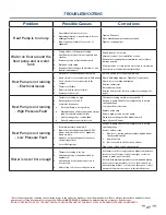
background image

27

TROUBLESHOOTING

Problem

Possible Causes

Corrections

Heat Pump is too noisy

1. 

Sheet Metal fasteners are loose.

2. 

Operating vibration is transferring to fl oor or 
building structure.

3. 

Blower pulley assembly loose or out of 
alignment

Tighten Fasteners

Place vibration dampers underneath unit

Tighten or align pulleys

Water on fl oor around the 

heat pump and or water 

tank

1. 

Tubing, valves, or fi ttings are leaking

2. 

Heat Pump is not leveled causing drain pan 
overfl ow

3. 

Condensate trap not installed properly

4. 

Drain pan overfl owing

5. 

Condensation forming on the bottom of unit 
(humid environments)

Repair leaks as necessary

Shim unit to level, See installation section

Condensate trap depth must maintain a water column 
during operation

Use pipe snake or compressed air to remove obstruction

Cover bottom of unit with foam insulation

Heat Pump is not running 

- Electrical issues

1. 

Circuit does not have adequate ampacity

2. 

Short circuit or loose connection in fi eld wiring

3. 

Short circuit or loose connection in the 
cabinet

4. Thermostat 

Failure

5. 

Defective anti-short cycle timer

6. Compressor 

burn-out

Refer to nameplate for unit requirements

Check fi eld wiring diagram, Tighten all connections

Check for loose wiring and tighten

Replace thermostat

Reset phase monitor

Replace Compressor (refer to compressor change-out 
page)

Heat Pump is not running 

- High Pressure Fault

1. 

Thermostat setting too high

2. 

Air temperature over 95

°

 F

3. 

Low water fl ow causes

a. 

 External Pump is not operating

b. 

Piping between the heat pump and storage 
tank exceeds 50 equivalent feet

c. 

Heat exchanger has scale buildup

d. Shut 

off  valves are partially closed

Thermostat setting should not exceed 160

°

 F

Keep heat pump off  until room temperature is back in 
operating range

Low water fl ow corrections

Replace unit pump

Reduce piping or add booster pump

Clean heat exchanger with a mild acid wash

Open all shut off  valves

Heat Pump is not running 

- Low Pressure Fault

1. 

Room temperature below 40

°

 F

2. 

Blower not operating at nameplate CFM - 
blower belt is broken or out of alignment 
fi lters are dirty

3. 

Unit does not have adequate clearances 
obstructing air fl ow

4. 

Loss of Refrigerant

Keep heat pump off  until room temperature is back in 
operating range

Correct air-fl ow issue

i. 

Replace or realign pulley assembly; tighten belt at 
the adjustable pulley

ii. Replace 

fi lters

iii. 

Relocate unit to allow for even air fl ow

Find source of leak, repair, and recharge

Water is never hot enough

1. 

Thermostat setting is too low

2. 

Heat pump/storage tank undersized for 
application

3. 

Heat pump is not properly connected to 
storage tank.

4. 

Unit cooling coil is over cooling the space

Set thermostat for storage tank to a higher temperature

Increase size of storage tank or install gas or electric 
heater to make up for shortfall

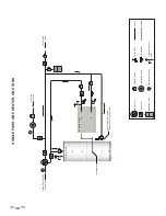
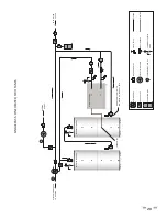
Refer to fi eld piping diagrams for recommended piping

If the room air temperature is too cool a) Use back up 
water heating  b) Duct  cool air to another space  c) duct 
warmer air from another space to the installed room

*Reset the heat pump by removing then restoring power to the unit at the breaker or from the manual switch. (There will be a three minute delay before heat 
pump restarts.) If the heat pump cuts out again on LOW or HIGH PRESSURE, additional troubleshooting is necessary to fi nd the cause. 

DO NOT CONTINUE TO RESET THE HEAT PUMP, AS CONTINUED SHORT-CYCLING MAY STRESS OR DAMAGE INTERNAL COMPONENTS

Summary of Contents for AHPM-270

Page 1: ...ion Manual Series 100 Models AHPM 270 AHPM 540 AHPM 810 AHPM 1080 AHPM 1350 AHPM 1620 AHPM 1890 AHPM 2160 Modular Water Source Commercial Heat Pump Water Heating Systems Certified UL 1995 2015 CSA C22...

Page 2: ......

Page 3: ...O MEMBER UNITS 22 MASTER CONTROL UNIT SUPPORT CALL SEQUENCE OF OPERATIONS 22 MEMBER SCREENS 23 SAFE INSTALLATION USE AND SERVICE 1 GENERAL SAFETY INFORMATION 2 PRECAUTIONS 2 GROUNDING INSTRUCTIONS 2 I...

Page 4: ...DDRESS CONFIGURATION 23 SINGLE UNIT HEAT BANK SCREEN 23 MEMBER SCREEN TERMINOLOGY 24 HOME SCREEN 24 ALARM SCREEN 24 CONFIGURATION SCREEN 24 STOP SCREEN 24 IP CONFIGURATION 24 MAINTENANCE AND SERVICE 2...

Page 5: ...hers who install use or service this heat pump water heater All safety messages will generally tell you about the type of hazard what can happen if you do not follow the safety message and how to avoi...

Page 6: ...External fire 2 Damage 3 Running without water GROUNDING INSTRUCTIONS This heat pump water heater must be grounded in accordance with the National Electrical Code and or local codes These must be foll...

Page 7: ...AGE Thismanualcontainsinstructionsfortheinstallation operation and maintenance of the heat pump water heater HPWH It also contains warnings throughout the manual that you must read and be aware of All...

Page 8: ...ustomer provided Water Pump circulates water through the condenser Refrigerant leaving the condenser is a medium temperature high pressure liquid It flows through the Liquid Line to the Thermostatic E...

Page 9: ...Circuit Heated Water Inlet Condenser Heat Exchanger Heated Water Outlet Figure 1 FEATURES COMPONENTS PRODUCT ILLUSTRATION Component Source Water Circuit Source Water Inlet Evaporator Heat Exchanger S...

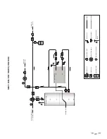
Page 10: ...6 Thermostatic Expansion Valve TXV Condenser Paddle Wheel Flow Sensor Accumulator Receiver...

Page 11: ...7 WATER TO WATER CYCLE...

Page 12: ...H AHPM 270 50 50 277 100 210 000 2 34 36 68 1 150 1 300 AHPM 540 100 100 554 200 414 450 2 64 36 68 2 300 2 600 AHPM 810 150 150 831 300 632 500 2 99 36 68 3 450 3 900 AHPM 1080 200 200 1 108 400 843...

Page 13: ...st conform to these instructions and all local and national code authority having jurisdiction Costs to diagnose perform service and repair damage caused by installation errors are not covered under t...

Page 14: ...0 or the Canadian Electrical Code CSA C22 1 Voltage applied to the HPWH should not vary more than 5 to 10 of the voltage requirement listed on the HPWH rating label for satisfactory operation TABLE 2...

Page 15: ...e heat pump water heaters are two wire circuits Three phase heaters are three wire circuits In addition to the foregoing a grounded conductor is required Not more than three conductors in raceway cabl...

Page 16: ...ion to using the lowest possible temperature setting that satisfies the demand of the application a Mixing Valve should be installed upstream from the building fixtures or at the hot water taps to fur...

Page 17: ...sistance in sizing of a temperature and pressure relief valve Follow the storage tank manufacturer s instructions regarding the proper installation of these products TANK SELECTION The HPWH unit is no...

Page 18: ...omponents are not moisture tolerant Note The limited warranty does not cover damage to the unit or controls due to negligence during storage The pictures may appear different than your actual unit all...

Page 19: ...g channels on the bottom of the unit See Table 1 on page 8 for unit dimensions and weights Note A qualified engineer should design and size the structural components of the mounting frame Structural c...

Page 20: ...ntrolled by a field supplied thermostat installed in the building recirculation return line near the storage tank or back up heater The thermostat should stop pump operation the moment the recirculati...

Page 21: ...line on the HPWH to help prevent scale build up in the heat exchanger Service costs to clear blockages from the HPWH unit s heat exchanger due to debris are not covered under the limited warranty ELEC...

Page 22: ...ey on the Touchscreen Monitor the refrigerant pressure hot water in and out temperatures and cold water in and out temperatures Itmaybehelpfultorecordtheoperatingdatainitiallyevery10 to15minutesjustto...

Page 23: ...ince they will always start and run in the proper direction Three phase compressors will rotate in either direction depending upon phasing of the power to L1 L2 and L3 Since there is a 50 50 chance of...

Page 24: ...inimum of water piping between the HPWH and the water system or tank Throttling should be done in small increments no more than 1 8 turn of the valve handle at a time The HPWH must be allowed to run f...

Page 25: ...TER PANEL ALARM SCREEN MASTER PANEL CONFIGURATION SCREEN MASTER SCREEN TERMINOLOGY HOME SCREEN LP Low Pressure indicates the suction line pressure on the low side of the system HP High Pressure indica...

Page 26: ...pDiff Temperature Difference sets the difference below the setpoint where the master will give a call for members to run SAVE button Saves the Tank Diff Set and System Timer parameters Master IP Addre...

Page 27: ...ME SCREEN OPERATING AS A SINGLE UNIT IN DEFROST SINGLE UNIT HOME SCREEN DISPLAYING ALARM SINGLE UNIT ALARM SCREEN SINGLE UNIT PIPE CONFIGURATION SCREEN SINGLE UNIT TANK CONFIGURATION SCREEN SINGLE UNI...

Page 28: ...n short cycling OUTLET FLOW indicates if the unit has alarmed out on condenser water flow Evap Flow indicates if the evaporator has flow M PROTECTION indicates if the unit has alarmed out on motor pro...

Page 29: ...l from the insulation using a vacuum device with a HEPA filter 99 97 efficient at 0 3 micron particles Be careful not to tear the insulation during the cleaning procedure 4 Apply the microbial cleanin...

Page 30: ...ould be 8 F to 12 F 4 4 C to 6 7 C BRAZE PLATE CLEANING INSTRUCTIONS In some applications the heat exchanger may be subjected to severe fluid conditions including high temperature hard water condition...

Page 31: ...d Shut off valves are partially closed Thermostat setting should not exceed 160 F Keep heat pump off until room temperature is back in operating range Low water ow corrections Replace unit pump Reduc...

Page 32: ...K ISOLATION VALVE CIRCULATING PUMP TEMPERATURE GAUGE WYE STRAINER TEMP PRESS RELIEF VALVE FLUSH VALVE PIPING WIRING ONLY USE BOTTOM LOWER CONNECTION IF TANK HAS TWO THERMOWELL HP WATER HEATER THERMAL...

Page 33: ...TION VALVE CIRCULATING PUMP TEMPERATURE GAUGE WYE STRAINER TEMP PRESS RELIEF VALVE FLUSH VALVE PIPING WIRING ONLY USE BOTTOM LOWER CONNECTION IF TANK HAS TWO HP WATER HEATER THERMOWELL THERMAL STORAGE...

Page 34: ...GAUGE WYE STRAINER TEMP PRESS RELIEF VALVE FLUSH VALVE PIPING WIRING ONLY USE BOTTOM LOWER CONNECTION IF TANK HAS TWO THERMOWELL HP WATER HEATER HP WATER HEATER MASTER CONTROL PANEL RECOMMENDED FOR MU...

Page 35: ...HECK VALVE EXPANSION TANK ISOLATION VALVE CIRCULATING PUMP TEMPERATURE GAUGE WYE STRAINER TEMP PRESS RELIEF VALVE FLUSH VALVE PIPING WIRING HP WATER HEATER THERMOWELL THERMAL STORAGE COLD WATER SUPPLY...

Page 36: ...SINGLE HEATER MIXING VALVE CHECK VALVE EXPANSION TANK ISOLATION VALVE CIRCULATING PUMP TEMPERATURE GAUGE WYE STRAINER TEMP PRESS RELIEF VALVE FLUSH VALVE PIPING WIRING SOURCE WATER SUPPLY SOURCE WATE...

Page 37: ...HEATER REVERSE RETURN MIXING VALVE CHECK VALVE EXPANSION TANK ISOLATION VALVE CIRCULATING PUMP TEMPERATURE GAUGE WYE STRAINER TEMP PRESS RELIEF VALVE FLUSH VALVE PIPING WIRING SOURCE WATER SUPPLY SOUR...

Page 38: ...en the heat pump water heater is installed in accordance with local plumbing and building codes ordinances and regulations the warrantor s printed instructions provided with it and good industry pract...

Page 39: ...35 500 Tennessee Waltz Parkway Ashland City TN 37015 Technical Support 1 833 447 3201 www hotwater com...

Page 40: ...36 Service Log Issue Description Date Servicer...

Page 41: ...Service Log Issue Description Date Servicer 37...

Page 42: ...Notes 38...

Page 43: ......

Page 44: ......

Reviews: