Gardner Denver FXD - 10", Operating And Service Manual
The Gardner Denver FXD - 10" Operating And Service Manual is available for free download on our website. This comprehensive manual provides detailed instructions and maintenance guidelines for the Gardner Denver FXD - 10" product. Visit manualshive.com now to access this invaluable manual and ensure optimal performance of your equipment.
Share
Download


Reviews:
No comments
Related manuals for FXD - 10"

D75
Brand: Davey Water Products Pages: 4

RC
Brand: Patterson Pages: 16

GPS400
Brand: Wayne Pages: 8

Boostamatic 4000
Brand: Stuart Pages: 20

PEP-II Series
Brand: Zenith Pages: 12

FXF - 5"
Brand: Gardner Denver Pages: 27

PT 3H
Brand: Wacker Neuson Pages: 64

YW20PTP
Brand: Yardworks Pages: 18

YW65PHP
Brand: Yardworks Pages: 19

SBP 2200
Brand: Kärcher Pages: 68

KC 10 Series
Brand: FTI Pages: 9

LGB1E
Brand: BLACKMER Pages: 12

Sequence Titan
Brand: MDM Pages: 5
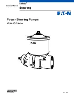
Vickers VT16
Brand: Eaton Pages: 11
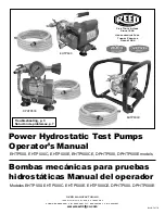
DPHTP500
Brand: REED Pages: 12
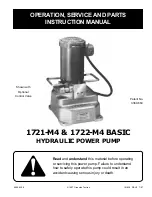
1722-M4
Brand: Greenlee Pages: 10

950-M3
Brand: Greenlee Pages: 10
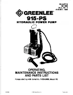
915-PS
Brand: Greenlee Pages: 16


